Continue to Site

Welcome to EDAboard.com

Welcome to our site! EDAboard.com is an international Electronics Discussion Forum focused on EDA software, circuits, schematics, books, theory, papers, asic, pld, 8051, DSP, Network, RF, Analog Design, PCB, Service Manuals... and a whole lot more! To participate you need to register. Registration is free. Click here to register now.

Effect of Xor gate on this circuit? Please help!

Status
Not open for further replies.

cadenceUK

Member level 5
Joined
Aug 15, 2007
Messages
90
Helped
1
Reputation
2
Reaction score
1
Trophy points
1,288
Activity points
1,862
Could any 1 detail about the working of this circuit?

special about the effect of XOR gate and transisters!
 

is d ckt 2 much cmplicated??

i jst asked wether the o/p of XOR will affect the main o/p? i mean .. will the transister tun on/off depending upon d o/p of XOR?
 

What is triangle component with AB inputs? Triangle with single input?
Why the low level of input signals is 1V (not 0V).
 

i think the o/p of the gate will certainly effect the overall out put i think i is some what complicated
 

The tringle component is a XOR gate and I want to increase the drive of the circuit in case of opposite bit patteren!

Added after 37 seconds:

and the trianlge with single input is a simple buffer/inverter!

Added after 1 minutes:

plz assume the low level as 0 volt! as i gave these 2 supplies just to give opposite inputs!

Thanks !!
 

I want to increase the drive of the circuit in case of opposite bit patteren!

You mean you want to increase high-level driving capability of XOR? Because for opposite input pattern XOR output is HIGH.

a simple buffer/inverter

What exactly: Buffer or inverter?
Buffer in contrast to inverter has opposite logic.
 

Fom said:
I want to increase the drive of the circuit in case of opposite bit patteren!

You mean you want to increase high-level driving capability of XOR? Because for opposite input pattern XOR output is HIGH.

a simple buffer/inverter

What exactly: Buffer or inverter?
Buffer in contrast to inverter has opposite logic.
Hi Fom,
Thanks for your response.

I want to increase the drive of the whole circuit ( as shown ) in case of high level output of XOR!


EG: If the input of XOR is high the 2nd ( inverter) transisters will increase the drive of circuit.

If it is low, the other inverter (transistor) will not work, but the single trianlge ( transister will work)!

Added after 35 seconds:

It is inverter!

Sorry fr the term buffer here!

Added after 4 hours 37 minutes:

Please help :( its last day of my project :*(
 

You cannot connect inverter output to XOR output.
Inverter has both pull-down and pull-up transistor and state of them depends on inverter input only, but state of XOR depends on both logic signals. So for some combination yiu will get shorted output condition with high trough current.
If you want to increase driving capability why not insert 2 large-size inverters.

Another thing: for standard logic CMOS process it is impossible both PMOS and NMOS to be isolated at the same time. I mean isolated when NWELL or PWELL can be isolated and connected to the source of every transistor.
 

    cadenceUK

    Points: 2
    Helpful Answer Positive Rating
Dear Fom,
Many thanks for your help.

I was trying to control pull up and pull down of another inverter circuit at the end ( of transisters) with my XOR gate.

However, from you reply it seems that my circuit is wrong.


I will need your help again i guess!

I need to split the driver into half!

1 is trianlge symbol of inverter

other is inverter schematic by transisters.

Now I want the output to be driven by 1 inverter in case of same bit patteren but want the 2nd inverter ( transister schematic) to increase the drive by adding it in case of opposite bit patteren.


Sorry for my english and lack of knowledge about this but i urgently need your help today .. as it is my last day of project ..Thanks!
 

Sorry but I cannot understand logic of your device.
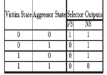
Can you give true table like this:

In1 In2 Out
0 0 ? (weak)
0 1 ? (strong)
1 0 ? (strong)
1 1 ? (weak)
 

    cadenceUK

    Points: 2
    Helpful Answer Positive Rating
Hi Fom!

Thx fr ur quick response.

A have splitted the inverter into two.

Say H into x+y

Now I want X+Y to function when the output of XOR is high.

i.e. in case of input = 0,1 or 1,0 ( opposite)

Otherwise only X ( triangle symbol 1st) will function and the Y( inverter with transister!) will not.

i.e. in case of input = 0,0 or 1,1 ( same)

Many thanks for your help!

This is last day of my project and I am going to talk wid my superviser in 2 hours!

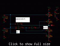
Here is the pic of my ckt!

Added after 4 minutes:


Added after 1 minutes:

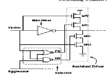
and this is the circuit I m modifying !!


21_1189501465.gif
 

Now I understand your idea.
Looks correct!
 

But I am not quite sure.. !
XOR gives output only on opposite patteren in my circuit!

However this circuit which i m trying to modify does not!

I am replacing this XOR O/P circuit with
59_1189511695.gif
 

You don't need XOR.
You need Victim signal should be inverted and if agressor is opposite the driving capability of Victim's inverter is HIGH.
You have it.
Why you need XOR.
 

XOR checks for the patteren!

If they are opposite only then it adds 2nd inverter to increase the drive stregth!

Added after 1 minutes:

XOR and the Truth table given above is for the control circuit which checks the opposite bit patteren!


& if Input patteren is opposite... hten it adds the other inverter with 1st increasing the drive strength!
 

Status
Not open for further replies.

Similar threads

Part and Inventory Search

Welcome to EDABoard.com

Sponsor

Back
Top