Continue to Site

Welcome to EDAboard.com

Welcome to our site! EDAboard.com is an international Electronics Discussion Forum focused on EDA software, circuits, schematics, books, theory, papers, asic, pld, 8051, DSP, Network, RF, Analog Design, PCB, Service Manuals... and a whole lot more! To participate you need to register. Registration is free. Click here to register now.

Help in Digital Converter with VHDL

Status
Not open for further replies.

YenYu

Member level 5
Joined
Jul 2, 2007
Messages
92
Helped
6
Reputation
12
Reaction score
0
Trophy points
1,286
Activity points
2,046
log10 vhdl

Hi pals,

Currently, i haf this problem. I wanted to down convert some IF signal.I have done quite an amount of my main program, left the last part which is my problem i'm facing. How should i implement the Direct Digital Synthesizer(DDS)? It works like that, my input,"Xi2 & Xr2", with a 120MHz will be compared with signal generated by DDS which has a sine and cosine wave, 125MHz. Output (It2 & Qt2) should be a 5MHz wave.
Saying ( Sine/Cosine (125MHz) - Xi2/Xr2 (120MHz) = It2/Qt2(5MHz) )

How to do it? I tried to implement the DDS as a component within My Down Converter but it isnt working. My Output is still 125MHz.
 

webpack dds compiler

If You're using ISE (programming Xilinx chip), try using appropriate Core Generator component.
 

vhdl m_pi

A basic DDS consists of a clocked accumulator with a constant input (the desired frequency), and a ROM containing one sinewave cycle. Connect the most significant bits of the accumulator to the ROM address inputs. The ROM output is your sinewave.

If you show us your code, maybe someone can help you debug it.
 

frequency sweep in vhdl testbench

Currently i near there, but there is something wrong with the timing i guess. The results were a'lil werild. Here is my Main program and Test Bench. Help pl0x =D!

Main Program-

library IEEE;
use IEEE.STD_LOGIC_1164.ALL;
use IEEE.STD_LOGIC_ARITH.ALL;
use IEEE.STD_LOGIC_UNSIGNED.ALL;
---- Uncomment the following library declaration if instantiating
---- any Xilinx primitives in this code.
library UNISIM;
use UNISIM.VComponents.all;

entity DownConverter is
Port ( m_clk,res : in STD_LOGIC; --Master Clock & Reset
X: in STD_LOGIC_VECTOR(9 downto 0); --10bit Input
Xr2,Xi2 : out STD_LOGIC_VECTOR(9 downto 0); --10bit Output
It2,Qt2 : out STD_LOGIC_VECTOR(26 downto 0) --27bit Output
);
end DownConverter;

architecture main OF DownConverter is
type state is (Start,S1,S2,S3,S4);
Signal Current_state,Next_state : State;
Signal Xr2i,Xi2i : STD_LOGIC_VECTOR(9 downto 0); --Internal Signal for DC
Signal sclr,clk : STD_LOGIC;
Signal rfd,rdy,nd: STD_LOGIC;
Signal dout,dout2: STD_LOGIC_VECTOR(26 downto 0);
Signal din,din2 : STD_LOGIC_VECTOR(9 downto 0);
-----------------------------------------------------------------------------------

--------------------------- Declare Component <Filter1> ---------------------------
Component filter is
port (
sclr : in STD_LOGIC;
rfd : out STD_LOGIC;
rdy : out STD_LOGIC;
nd : in STD_LOGIC := '1';
clk : in STD_LOGIC;
dout : out STD_LOGIC_VECTOR ( 26 downto 0 );
din : in STD_LOGIC_VECTOR ( 9 downto 0 )
);
end Component;
----------------------------------------------------------------------------------

-------------------------- Declare Component <Filter2> ---------------------------
Component filter2 is
port (
sclr : in STD_LOGIC;
rfd : out STD_LOGIC;
rdy : out STD_LOGIC;
nd : in STD_LOGIC := '1';
clk : in STD_LOGIC;
dout : out STD_LOGIC_VECTOR ( 26 downto 0 );
din : in STD_LOGIC_VECTOR ( 9 downto 0 )
);
end Component;
----------------------------------------------------------------------------------


begin
-------------------- Component Instantiation Filter 1 --------------------
u2:component Filter Port Map (din=>din,
dout=>dout,
clk=>m_clk,
sclr=>res,
rfd=>rfd,
rdy=>rdy,
nd=>nd
);
--------------------------------------------------------------------------

-------------------- Component Instantiation Filter 2 --------------------
u3:component Filter2 Port Map (din=>din2,
dout=>dout2,
clk=>m_clk,
sclr=>res,
rfd=>rfd,
rdy=>rdy,
nd=>nd
);
--------------------------------------------------------------------------

process ( m_clk,res )
begin
if res='1' then
Current_state <= Start;
elsif (m_clk'event and m_clk='1') then
Current_state <= Next_state;
end if;
end process;

process ( Current_state,X )
begin

case Current_state is
when Start=> Next_state <= S1;
Xr2i<= X ; Xi2i<= "0000000000";
when S1 => Next_state <= S2;
Xr2i<= "0000000000" ; Xi2i<= 0-X;
when S2 => Next_state <= S3;
Xr2i<= 0-X ; Xi2i<= "0000000000";
when S3 => Next_state <= S4;
Xr2i<= "0000000000" ; Xi2i<= X;
when S4 => Next_State <= S1;
Xr2i<= X ; Xi2i<= "0000000000";

end case;
end process;
nd<= '1';
Xr2<=Xr2i;
Xi2<=Xi2i;
Din<=Xr2i;
Din2<=Xi2i;
It2<=Dout;
Qt2<=Dout2;
end;


Test Bench-

LIBRARY ieee;
USE ieee.std_logic_textio.ALL;
USE ieee.std_logic_1164.ALL;
USE ieee.numeric_std.ALL;
USE std.textio.ALL;

-- Entity
ENTITY DownTB IS
END;

-- Architecture
ARCHITECTURE TB OF DownTB IS

-- Component Declaration
---------------- Declare Component <Down Converter>-----------------------------
COMPONENT DownConverter
PORT(
m_clk: IN std_logic; -- Master Clock
res: IN std_logic; -- Master Reset
X: IN std_logic_vector(9 downto 0); -- Input
It2,Qt2 : OUT STD_LOGIC_VECTOR(26 downto 0); -- 27bit Output
Xr2,Xi2 : OUT std_logic_vector(9 downto 0) -- 10bit Output
);
END COMPONENT;
--------------------------------------------------------------------------------

---------------- Declare Component <Direct Digital Synthesizer>-----------------
COMPONENT dds IS
PORT (
clk : IN STD_LOGIC;
sclr : IN STD_LOGIC;
Sine : OUT STD_LOGIC_VECTOR(9 DOWNTO 0)
);
END COMPONENT;
--------------------------------------------------------------------------------

For u1: DownConverter use entity work.DownConverter(Main);

SIGNAL m_clk : std_logic:='1'; -- Master Clock
SIGNAL d_clk :std_logic:='1'; -- DDS Clock Rate at 500MHz
SIGNAL res : std_logic:='1'; -- Master Reset
SIGNAL X: std_logic_vector(9 downto 0);
SIGNAL Xr2,Xi2 : std_logic_vector(9 downto 0);
SIGNAL Sine: std_logic_vector(9 downto 0);
SIGNAL It2,Qt2:std_logic_vector(26 downto 0);

BEGIN

----------------- Component Instantiation Down Converter -----------------
u1: DownConverter PORT MAP(m_clk=>m_clk,
res=>res,
X=>X,
Xr2=>Xr2,
Xi2=>Xi2,
It2=>It2,
Qt2=>Qt2
);
--------------------------------------------------------------------------

----------- Component Instantiation Direct Digital Synthesizer -----------
u4: dds PORT MAP (clk=>d_clk,
sclr=>res,
Sine=>Sine
);
--------------------------------------------------------------------------

X <= Sine;
res <= '1','0' after 2 ns;
m_clk <= not m_clk after 1 ns; --Master Clock
d_clk <= not d_clk after 1 ns; --DDS Clock
end;


It's alil messy... i Copied out from XIlinx straight. Thx !
 

hex2dec vhdl

I see no calculation, no substance. It's like an empty shell.
 

reading from a mif file on vhdl

There's no need calculation in this down converter. It's a down converter which i did it myself and basically there is 3 things from COREGEN, the 2 filter and 1 DDS. DDS in my coding will work as a source. The output of the DDS is a 125MHz Sine output. Then it will go to the input of the down converter X, giving 2 output It2 & Qt2 which is wat i should obtain with a 5MHz wave. Xr2 & Xi2 are 10Bits output with a certain pattern. With this it should basically down convert a 120Mhz-125MHz wave down to a 5MHz wave.
 

virtex block ram vhdl program example

is there the whole codes?
 

vhdl hex2dec

This is the whole code already.... the rest is just generated from COREGEN, Filter and Direct Digital Synthesizer. Now here's the rough idea, the DDS will provide a sine wave and will go to the input of my DownConverter, Which will down convert the sine wave from 125Mhz to 5Mhz.
 

how to create a frequency converter in vhdl

OK, I hope I got it: create counter from 0 to 24 and every time counter gets to "all zeroes" state change the values of Your output signals (those that should be on 5MHZ), otherwise don't change them. This is how You make 25 identical samples at the output, while working on 125MHz, meaning - You create 5MHZ signal. But...
That signal won't be sine wave, it'll be awful-let's-say-sampled-sine-wave. You need to filter it with analog filter to make useful sine wave from that, or You can forget whole this story and solve this problem in form of LUTs. That's what I would do.
 

matlab vhdl filter broken

Yep, i Did at 2 Filters into my program. I got a smooth sine wave with 5MHz using 120MHz of DDS output wave. But when i tried out some other freq, for example 121MHz, thought i get a smooth one too, but in between there is some spikes shown. How to i solve that problem ?


Thx For Help ppl! ^^
 

vhdl code fir filter 100mhz

If those "spikes" are present at filter's output, try with narrower passband.
 

vhdl .mif example

Oh, Thx. But wat does the passband u are reffering to?
 

digital low pass filter in vhdl

I'm not sure what your spikes look like, but if they disappear when you decrease the signal amplitude, then maybe the arithmetic is overflowing.
 

normalized period + xilinx blocks

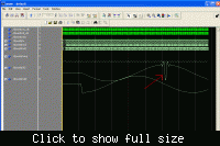
This is how my waveform looks like with 122MHz. It Has spike within the wave.


freqz matlab to scilab conversion

Yes, that looks like arithmetic overflow. A large positive value overflows, and becomes a large negative value. To find where it's occurring, try viewing the signal at various points along your signal processing stages.
 

vhdl idelay

Hmm, Thx for ur help..
But there's way too many signals in the DDS component. Possible so list some common problems on the arithmetic overflow for DDS?
 

modelsim simulation libraries dds compiler v2.0

Hi,
After trying many ways of solving this problem, I still cant manage to solve the spikes. Anyone could help? How do i lower the amplitude of the wave?
 

dds compiler example

Overflow can occur during any arithmetic or data transfer step.

To lower the signal's amplitude, try dividing it by 2. That's a simple right-shift.

If you can show us your complete code, someone here can probably help you debug it. The code you posted above is not the right stuff. It doesn't show any of the signal processing.
 

Okay, here's my complete Main program and TestBench
The Filter,Filter2 and DDS is generated from CoreGen

***Main Program***
library IEEE;
use IEEE.STD_LOGIC_1164.ALL;
use IEEE.STD_LOGIC_ARITH.ALL;
use IEEE.STD_LOGIC_UNSIGNED.ALL;
---- Uncomment the following library declaration if instantiating
---- any Xilinx primitives in this code.
--library UNISIM;
--use UNISIM.VComponents.all;

entity DownConverter is
Port ( m_clk,res : in STD_LOGIC; --Master Clock & Reset
X : in STD_LOGIC_VECTOR(9 downto 0); --10bit Input
Xr2,Xi2 : out STD_LOGIC_VECTOR(9 downto 0); --10bit Output
It2,Qt2 : out STD_LOGIC_VECTOR(26 downto 0) --27bit Output
);
end DownConverter;

architecture main OF DownConverter is
type state is (Start,S1,S2,S3,S4);
Signal Current_state,Next_state : State;
Signal Xr2i,Xi2i : STD_LOGIC_VECTOR(9 downto 0); --Internal Signal for DC
Signal sclr,clk : STD_LOGIC;
Signal rfd,rdy,nd: STD_LOGIC;
Signal dout,dout2: STD_LOGIC_VECTOR(26 downto 0);
Signal din,din2 : STD_LOGIC_VECTOR(9 downto 0);
-----------------------------------------------------------------------------------

--------------------------- Declare Component <Filter1> ---------------------------
Component filter is
port (
sclr : in STD_LOGIC;
rfd : out STD_LOGIC;
rdy : out STD_LOGIC;
nd : in STD_LOGIC := '1';
clk : in STD_LOGIC;
dout : out STD_LOGIC_VECTOR ( 26 downto 0 );
din : in STD_LOGIC_VECTOR ( 9 downto 0 )
);
end Component;
----------------------------------------------------------------------------------

-------------------------- Declare Component <Filter2> ---------------------------
Component filter2 is
port (
sclr : in STD_LOGIC;
rfd : out STD_LOGIC;
rdy : out STD_LOGIC;
nd : in STD_LOGIC := '1';
clk : in STD_LOGIC;
dout : out STD_LOGIC_VECTOR ( 26 downto 0 );
din : in STD_LOGIC_VECTOR ( 9 downto 0 )
);
end Component;
----------------------------------------------------------------------------------

begin
-------------------- Component Instantiation Filter 1 --------------------
u2:component Filter Port Map (din=>din,
dout=>dout,
clk=>m_clk,
sclr=>res,
rfd=>rfd,
rdy=>rdy,
nd=>nd
);
--------------------------------------------------------------------------

-------------------- Component Instantiation Filter 2 --------------------
u3:component Filter2 Port Map (din=>din2,
dout=>dout2,
clk=>m_clk,
sclr=>res,
rfd=>rfd,
rdy=>rdy,
nd=>nd
);
--------------------------------------------------------------------------

process ( m_clk,res )
begin
if res='1' then
Current_state <= Start;
elsif (m_clk'event and m_clk='1') then
Current_state <= Next_state;
end if;
end process;

process ( Current_state,X )
begin

case Current_state is
when Start=> Next_state <= S1;
Xr2i<= X ; Xi2i<= "0000000000";
when S1 => Next_state <= S2;
Xr2i<= "0000000000" ; Xi2i<= 0-X;
when S2 => Next_state <= S3;
Xr2i<= 0-X ; Xi2i<= "0000000000";
when S3 => Next_state <= S4;
Xr2i<= "0000000000" ; Xi2i<= X;
when S4 => Next_State <= S1;
Xr2i<= X ; Xi2i<= "0000000000";

end case;
end process;
nd<= '1';
sclr<=res;
Xr2<=Xr2i;
Xi2<=Xi2i;
Din<=Xr2i;
Din2<=Xi2i;
It2<=Dout;
Qt2<=Dout2;
end;


***TestBench***
-- TestBench Template
LIBRARY ieee;
USE ieee.std_logic_textio.ALL;
USE ieee.std_logic_1164.ALL;
USE ieee.numeric_std.ALL;
USE std.textio.ALL;

-- Entity
ENTITY DownTB IS
END;

-- Architecture
ARCHITECTURE TB OF DownTB IS

-- Component Declaration
---------------- Declare Component <Down Converter>-----------------------------
COMPONENT DownConverter
PORT(
m_clk : IN std_logic; -- Master Clock
res : IN std_logic; -- Master Reset
X : IN std_logic_vector(9 downto 0); -- Input
It2,Qt2 : OUT STD_LOGIC_VECTOR(26 downto 0); -- 27bit Output
Xr2,Xi2 : OUT std_logic_vector(9 downto 0) -- 10bit Output
);
END COMPONENT;
--------------------------------------------------------------------------------

---------------- Declare Component <Direct Digital Synthesizer>-----------------
COMPONENT dds IS
PORT (
clk : IN STD_LOGIC;
sclr : IN STD_LOGIC;
rfd : OUT STD_LOGIC;
rdy : OUT STD_LOGIC;
Sine : OUT STD_LOGIC_VECTOR(9 DOWNTO 0)
);
END COMPONENT;
--------------------------------------------------------------------------------

-- For u1: DownConverter use entity work.DownConverter(Main);

SIGNAL m_clk : std_logic:='1'; -- Master Clock
SIGNAL d_clk : std_logic:='1'; -- DDS Clock Rate at 500MHz
SIGNAL res : std_logic:='1'; -- Master Reset
SIGNAL X : std_logic_vector(9 downto 0);
SIGNAL Xr2,Xi2 : std_logic_vector(9 downto 0);
SIGNAL Sine : std_logic_vector(9 downto 0);
SIGNAL It2,Qt2 : std_logic_vector(26 downto 0);
SIGNAL rfd,rdy : std_logic;

BEGIN

----------------- Component Instantiation Down Converter -----------------
u1: DownConverter PORT MAP(m_clk=>m_clk,
res=>res,
X=>X,
Xr2=>Xr2,
Xi2=>Xi2,
It2=>It2,
Qt2=>Qt2
);
--------------------------------------------------------------------------

----------- Component Instantiation Direct Digital Synthesizer -----------
u4: dds PORT MAP (clk=>d_clk,
sclr=>res,
rdy=>rdy,
rfd=>rfd,
Sine=>Sine
);
--------------------------------------------------------------------------

X <= Sine;
res <= '1','0' after 0.1 ns;
m_clk <= not m_clk after 1 ns; --Master Clock
d_clk <= not d_clk after 1 ns; --DDS Clock
end;

Added after 9 minutes:

This is the coe File that both my filter use.

This is the Full Specification i used for my DDS
DDS CoreGen Spec :
Function : Sine
DSS Clock Rate : 500MHz
Spurious Free Dynamic Range : 60
Frequency Resolution : 0.1165
Output Frequency : 120MHz-125Mhz (Fixed)
Phase Offset Angel : 0.0 (Fixed)
SClr Pin Enabled
Noise Shaping : Auto
Memory Type : Auto
Rdy and Rfd Pins Enabled
Pipelined Enabled
Accumulator Latency : One Cycle
 

Are you able to build a complete working project from scratch by using only that information?

How about simply uploading your ISE project? (Maybe run "Cleanup Project Files" and then "Archive".)
 

Status
Not open for further replies.

Part and Inventory Search

Welcome to EDABoard.com

Sponsor

Back
Top