Continue to Site

Welcome to EDAboard.com

Welcome to our site! EDAboard.com is an international Electronics Discussion Forum focused on EDA software, circuits, schematics, books, theory, papers, asic, pld, 8051, DSP, Network, RF, Analog Design, PCB, Service Manuals... and a whole lot more! To participate you need to register. Registration is free. Click here to register now.

How to use exported equivalent circuit of ansoft Q3D?

Status
Not open for further replies.

LTCC

Member level 1
Joined
Jun 20, 2007
Messages
34
Helped
0
Reputation
0
Reaction score
0
Trophy points
1,286
Activity points
1,523
q3d subckt

Hi, all
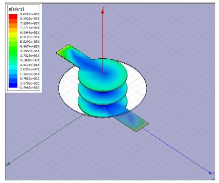
I've build a model in ansoft Q3D,when the simulation is finished,I right click Analysis to export the equivalent circuit, the format of the file is *.cir.

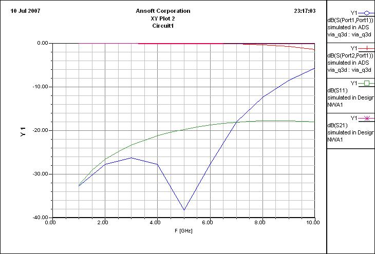
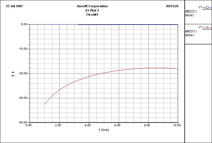
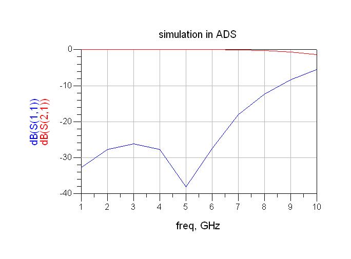
The problem is I don't know how to use this *.cir file in ansoft designer or other softwares,so I can see how the quilvalent circuit is and do some comparison with the results of HFSS.

Any advice would be helpful.

LTCC
 

q3d export formats

i think the .cir is a spice format , which is a spice netlist file . so u can open the .cir file with a wordpad or any text editor , and then draw the circuit on the designer

khouly
 

    LTCC

    Points: 2
    Helpful Answer Positive Rating
ansoft q3d

Thank you for Khouly.
Isn't any automatic way to do this?
 

use .cir file in ads

check the circuit dropdown menu in ansoft designer , and try to import it as a model , netlist file

i am not sure if this work or not ,

but i have ADS u can easily import the file and convert it to schematic

khouly
 

    LTCC

    Points: 2
    Helpful Answer Positive Rating
equivalent circuit export

The following is the content in *.cir file.But I don't know what the nodes in the subckt segment stand for,such as 0,1,2,3,4.Would you help me to draw the circuit?

* BEGIN ANSOFT HEADER
* node 1 Box1:Source1
* node 2 Box1:Sink1
* Project: via_gsg
* Format: Ansoft Designer
* Topckt: viaModel1
* Left: 1
* Right: 2
* Creator: Ansoft Q3D Extractor 6.0
* Date: Tue Jul 10 19:50:02 2007
* END ANSOFT HEADER

.subckt viaModel1 1 2
XZhalf1 1 3 viaModel1_half
XY1 3 viaModel1_parlel
XZhalf2 3 2 viaModel1_half
.ends viaModel1

.subckt viaModel1_half 1 2
V1 1 3 dc 0.0
R1 3 4 0.0083728141
L1 4 2 8.2601859e-010
.ends viaModel1_half

.subckt viaModel1_parlel 1
C1_0 1 0 5.081879e-013
.ends viaModel1_parlel

This is the model I built.
10_1184068968.jpg
 

Thank you so much for khouly, taking your advice,I make another try.
I have imported the *.cir file to ADS, and make the comparison with the simulation in designer which contains the Q3D design as a subcircuit.
But the two simulation results are different.

The following is the imported design in ADS and two simulaiton results:
59_1184112966.jpg


81_1184113004.jpg


76_1184112934.jpg
 

i see that u make ADS simulation ,but the results from the designer

where are the ADS simulation result

khouly
 

    LTCC

    Points: 2
    Helpful Answer Positive Rating
The last graph is the comparison of the two results and you can see the column in the right,it saied simulation in ADS,the blue one is S11 in ADS.

The following are two simulations dividually in ADS and designer.
69_1184205253.jpg

8_1184205787.jpg
 

Can anybody help me? Thank you!
 

it is strange , how two inditcal passive circuits , give different simulation results

khouly
 

you can use the *.cir file un PSPICE of cadence, it is a netlist, it is just the subcircuit containing tha SPICE equivelent circuit of your model. but in Q3D you can also change the the export file to other extentios, if I remember well you can exporto to RLC circuit model, and some others. what do you need the circuit for? to compare the results with HFSS? in HFSS you can also export the circuit and use SPICE to simulate. hope this helps.
 

please someone explain how to extract the circuit model of HFSS result?
 

Status
Not open for further replies.

Part and Inventory Search

Welcome to EDABoard.com

Sponsor

Back
Top