Continue to Site

Welcome to EDAboard.com

Welcome to our site! EDAboard.com is an international Electronics Discussion Forum focused on EDA software, circuits, schematics, books, theory, papers, asic, pld, 8051, DSP, Network, RF, Analog Design, PCB, Service Manuals... and a whole lot more! To participate you need to register. Registration is free. Click here to register now.

Help me IC555 Asymmetric Timer design for 220v FAN

Status
Not open for further replies.
T

tong

Guest
how can work ic 555

I search around NET and found that IC555 can work as Asymmetric Timer.
I would like to control 220v FAN power on 60 mins. then Off 30 mins. and so on in periodic until I unplug them.

I think the last circuit (the one that have diode) is best suit for me.

Tm = 0.7 × R1 × C1
Ts = 0.7 × R2 × C1

But I don't know maximum and minimun of the values.
What is the highest value of Tm, Ts, C1, R1, R2 ?

I plan to use C1 = 1000µF 16v
R1 = 5142857.14
R2 = 2571428.57

Is these correct ?

**broken link removed**
 

timer fan 4060

Pin 6 Threshold
Pin 6 is one input to the upper comparator (the other is pin 5). It makes the OUTPUT PIN go LOW.
To make the output go LOW, the Threshold pin is taken from a LOW to a level above 2/3 of rail voltage. This pin is level-sensitive, allowing slow rate-of-change waveforms to be detected.
A dc current, termed the threshold current, must also flow into this pin from the external circuit. This current is typically 0.1µA, and will determine the upper limit of total resistance allowable from pin 6 to rail. For 5v operation the resistance is 16M. For 15v operation, the maximum resistance is 20M.
This should give you indication on the max allowable combined resistance (R1+R2) ..
As far as capacitor is concerned, standard 1000µF electrolytic capacitors have substantial leakage current (usually specified as 0.01Cv or ≈3µA, whichever is greater) and MΩ resistors in the R-C tank may not be able to charge them to 2/3 of Vcc ..
From that point of view, 1000µF is most likely to big, but, whatever you do, use industrial grade, low leakage current caps ..

Regards,
IanP
 

timer design 220v

Too lazy to go through the math, but my advice would be to try out the circuit on a breadbord and see if it works as you expect. Use shorter time interval first and use a low voltage light or something on the relay.

Few more comments:
1. Electrolytic capacitor has very wide capacitance variation. If you get a 1000uF cap, it could vary -20% to +100% or more.
2. You should use a standard value resistor. For example, you might be able to find 2.4Meg and 510K ohm resistors. You can use smaller value resistor and add variable resistor in series if you want to "tune" the time. Resistors also have variation, 1%, 2% & 5% being common.
3. Using the 555 (especially for very long time period) is not very accurate.
 

asymmetric timer

Note in Thailand we have only 10uF Tantalum Bead.

So the R1 and R2 should be 270M (no diode).

Maybe it can't make over 30 minutes.

I found a page 555 calculator:
**broken link removed**
 

Hi Tong,

The values for the timing components are getting too extreme, therefore
you should consider a different approach. An RC oscillator and a divider
chain is one of many possible solutions.
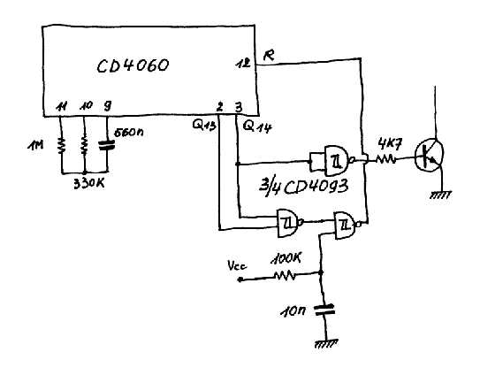
With the given values the oscillator period will be approximately
2,2 * 330E3 * 560E-9 = 406 mS. After switching it on the relay will
pull in and after 8192 clock pulses the relay will fall off. After
another 4096 pulses the circuit will reset itself and the timing cycle
will restart from the beginning.
The relay will stay pulled in for 8192 * 406 mS = 3330 S and the delay
for the cycle to restart will be another 4096 * 406 mS = 1665 S.
If you increase the 330 k resistor to 360 k, the "on" time will increase
to 3633 S and the "off" time will increase to 1817 S which is close enough
to 3600 S and 1800 S.

on1aag.

49_1183268152.gif
 

tong
forget 555 chip. It is not possible to solve your problem with it.
Above circuit with 4060 chip is propper solution.
 

Well, R-C method can't work in extreme wide period.

So the 4060 (builtin oscillator + counter) is a best choice.

Note: I found some C low leakage in Thailand.
It's aluminum electrolize
( I=0.002CV or 0.4uA, whichever is greater )
 

555 can operate on 15 V max for a long time period. If voltage is higher than 15 V 555 timer will burn out.
 

I would like the Relay working when power ON.
I want it freely adjust ON and OFF time intervel.

The bottom chip is ON timer.
The top chip is OFF timer.

The diode help us to stop oscillation until the OFF-chip timeout.
When OFF-chip timeout, it will reset ON-chip by short the capacitor.

Does these circuit work ?

**broken link removed**
 

Hi Tong,

The connection of both bases of the PNP transistor and the NPN transistor
is certainly wrong, your supply voltage will be short-circuited by the
two base-emitter junctions.
The connection of the collector of that NPN transistor to pin 8 of the
4060 is also wrong, pin 8 is GND. I think you want to release the reset
of that 4060, you better use some 4093 gates to do that, then you can
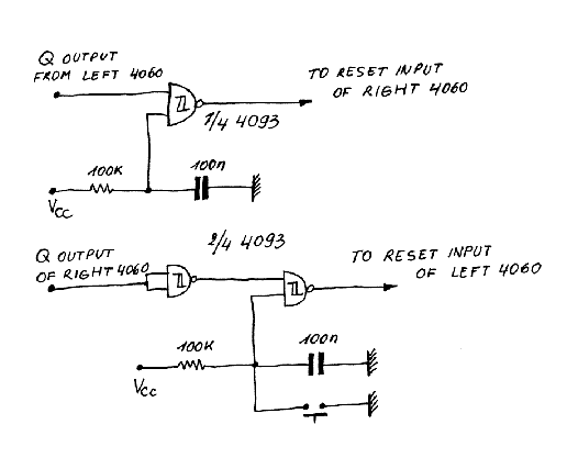
include the power-on-reset like I did in my circuit.

The same goes for the second NPN transistor which resets the first 4060.
When this happens the NPN transistor shorts the 100 nF capacitor of the
power-on-reset and that's tricky business.

on1aag.

47_1183353059.gif
 

Status
Not open for further replies.

Similar threads

Part and Inventory Search

Welcome to EDABoard.com

Sponsor

Back
Top