Continue to Site
Follow along with the video below to see how to install our site as a web app on your home screen.
Note: This feature may not be available in some browsers.
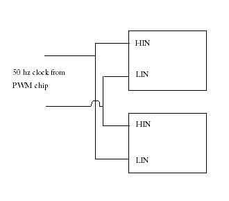
IanP said:Take a look at the attached circuit ..
You can modify it to suit your needs, but the idea is there ..
Regards,
IanP
eanic said:
Hi,KRYCHEK said:hi am wondering if anyone can help me.
Am building an high frequency switching inverter using the tl494,and using a H bridge,
can anyone assist me on how the H bridge converts dc back into ac, i mean how do i do this, and how do i get 50hz from this, many thanks
12vdc.....tl494...push-pull mosfets....transformer...bridge rectifier...h bridge...lc filter..
what i need to know is how to switch 2 on and 2 off at same time resulting in ac 220v 50hz, if u know
what i mean
this is a mod-sine wave btw
many thanks