Continue to Site

Welcome to EDAboard.com

Welcome to our site! EDAboard.com is an international Electronics Discussion Forum focused on EDA software, circuits, schematics, books, theory, papers, asic, pld, 8051, DSP, Network, RF, Analog Design, PCB, Service Manuals... and a whole lot more! To participate you need to register. Registration is free. Click here to register now.

[SOLVED] SWITCH MODE ARC INVERTER WELDER SCHEMATIC

Status
Not open for further replies.
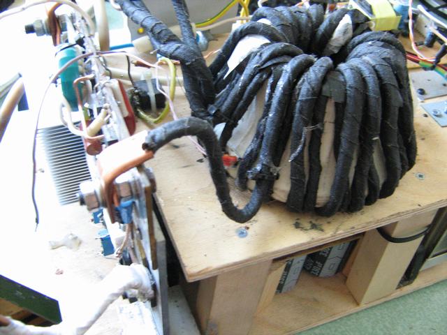
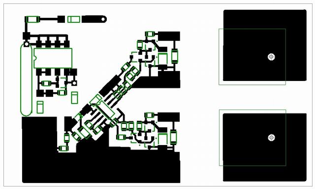
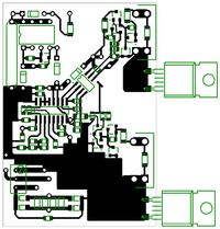
L1&L2 this is a two whorls around wire if we speak of same. And this is optional.

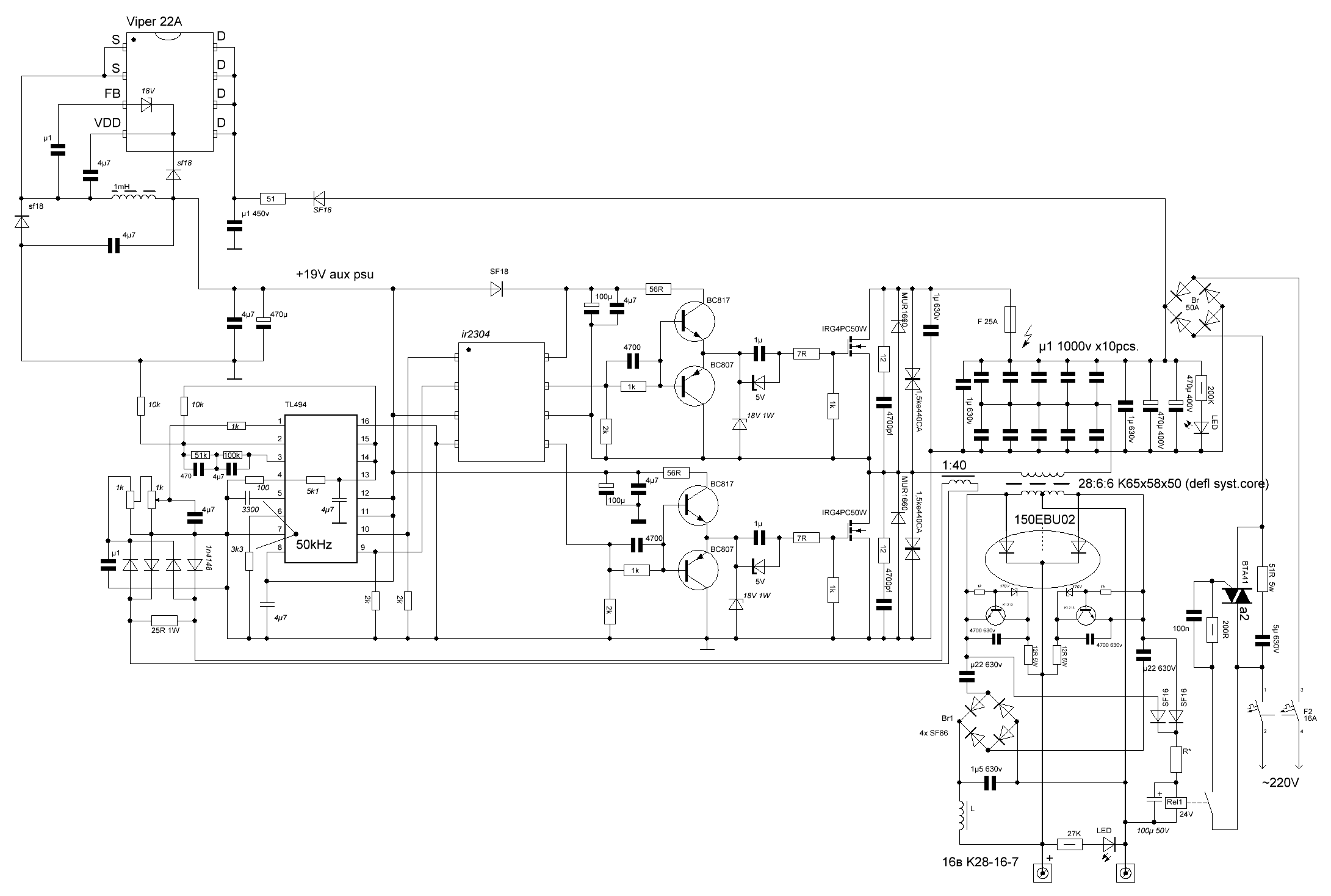
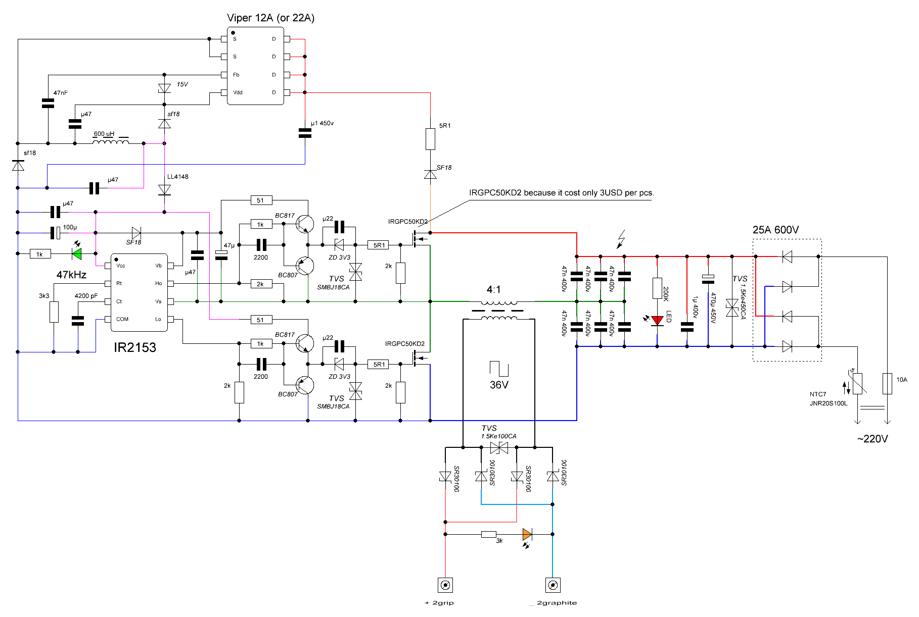
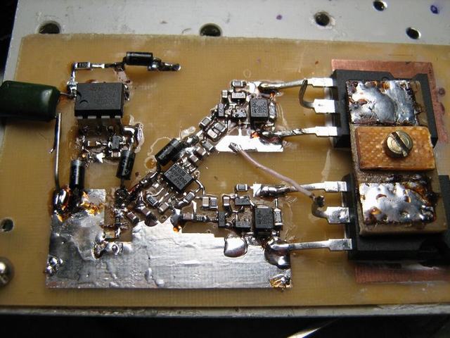
Apropos else another variant of the welding device but that not completed
 
Hi DeepOne,

Like idea of using TV deflection yoke, any more progress with this ??
 

Hi, Scotty.
TV deflection yoke is works very well in different purpose, including devices for arc welding.

Also has checked in work this part of scheme - - it works quite well.
 
Last edited:
Hi for ALL,
can somebody share with me schematic of CEMONT PUMA 1700G MMA?
thanks and
best regards
 

TV deflection yoke is works very well
regrettably, since several times (like year) that cores from TV deflection yoke in welding transformers is degrade and inductance of the transformer on their base decreases.

I have a scheme of CEMONT S1000 MMA (PWM SG3525) but for CEMONT PUMA 1700G MMA regrettably i has not found that.
 
  • Like
Reactions: pasicr

    pasicr

    Points: 2
    Helpful Answer Positive Rating
Can i please get the details of the transformer which gives 130Amps output.. I need to make one so i need the details like which bobbin, winding details etc..
 

You may use this program for transformer calculation

apropos the last version of device for welding copper wire -
 
Last edited:

For example calculation result for ETD49 core.

Because "winding fill" parameter exceed 1 this core is not suitable and need to get bigger, as you may see in picture )
 
Last edited:

Sizing of the transformer depends from frequency, cooling efficiency, wires characteristic, and many other things.
Aproximately, it is necessary for this something like R87.0/54.3/13.5(mm)N87 core.
 
I'm ressurecting this thread.
I've experimented with a couple of crt ferrites, the beam deflection ones, I blew up some low esr caps trying to get the core to saturate, couldnt manage it.
If you still frequent this forum deep one please expand on what you meant about core degradation, are you saying that these defrlection ferrites are unsuitable, presumably its not a shelf life issue, more of a flux density issue, ie cant take the wack.
I like the core calculation program, very usefull.
 

expand on what you meant about core degradation
One of my welding devices is blowing up (in IGBT part) when i do fabrication of the awning for my car.
Study of the problem has revealled essential fall of inductances of the transformer on this and on another one similar welding device. Since passed much time thereafter i already not remember some of details about it. In my suggestion that core degradation occurs by reason of core overheat.
core calculation program, very usefull
in this place else many programs for core calculations -
https://radiokot.ru/forum/viewtopic.php?f=11&t=33756
 
Last edited:

Ok so what your saying is that these TV deflection coil cores change their permeability if heated up.
So I can only use them if the application doesnt get hot.

Excellent link, I have downloaded most of those, I allready have the forward converter calc but not the flyback version, excellent thankyou, I'll use these for future projects.

For other readers of this thread the link posted above is in russian, but if you scroll down theres a post that links you to several computer design programs for transformers, and they are in english and well worth a visit.
 
Last edited:

Hi. i know that this tread is old but I need help.
I have a problem with this welder project http://danyk.cz/svar_en.html
My IGBT burns out. I crashed 3 of them, 2 pc. IRG4PC40W and one pc of 200A igbt.
My question is : Why? I need air gap to my power transformer? If else tell me please.

Thanks
 

here you have a treasure off schematics for all power inverter/chargers etc.

http://valvolodin.narod.ru/schems1.html

- - - Updated - - -

Hi. i know that this tread is old but I need help.
I have a problem with this welder project http://danyk.cz/svar_en.html
My IGBT burns out. I crashed 3 of them, 2 pc. IRG4PC40W and one pc of 200A igbt.
My question is : Why? I need air gap to my power transformer? If else tell me please.

Thanks

try to not get your core saturated, this happens I think and that give a schort circuit for the igbt,s.

some trafo,s have a air gap others not, I hace a E71 core without a air gap, but when use a gap of say 0.4 mm
the core get not saturated easely.

Do you let the signals get right on the gates? inverted? otherwise boooomm, saturation, that is why I prefere capacitive
way of connection off mosfets, so the core get not dc what will saturate them in a instant blow the igbs.

regards

kees

- - - Updated - - -

here is a example to prevent saturation in a full bridge, just use caps between trafo and bridge, I like this aproach, yes I now these caps are in stress so do not use elco,s here but parallel 10 x 1 uf 650/1000 volts mkt.

http://valvolodin.narod.ru/schems/forsag_sch.pdf
 

Hi Deep one, if you still frequent this forum.

You might be pleased to know that I have indeed read up and built a couple of smps's, including a couple off line ones.

Excellent it calculator and the flyback version is very good for this.

I want to build an smps suitable for starting and running a 12v vehicle engine from 240v mains without a battery, so I need continuous 25a or so and 150 to 200a for 10 seconds to start.

I have 2 flyback cores which are exactly the samem I was thinking of using these tied together as the core, is this a good idea?, my other option is I can get hold of a dead 2000w server smpsu, it will have some sizeable ferrites in it for salvage.
 

Hi, dr Pepper.
Anyway i had mail notification about new answers.
is this a good idea?
may be yes, may be not - that depends from many things.

Yarlier i have taken IR2153 or SG3525 or something similar for such task, but at this time i think the mcu pwm generation is better from standpoint of predictable behaviour, stability, resistance to hindrances and flexibility.
 
Last edited:

Hello deep one, pleased to see you still frequent the forum, even if by email reminders.

Ok then so I guess I'll have to try some lopt transformer cores and see what happens. I was thinking about building a simple jig to show the b/h curve of these cores. Another test I thought was to build a push pull circuit with just a primary and test the magnetization current, and see if the core warms up.

Your right about using a micro, you have full control, however if some care is taken a smps chip is still useable.

I see on you latest schematic your using a 'boosted zener' a transistor clamp to keep the o/p from overvolting the diodes, does this work ok?
On your first welder schematic you have a capacitively coupled bridge rectifier on the ooutput of the welder, and then it looks like this is fed back to the welder output again through an inductance, what is the thinking behind this?
 

Status
Not open for further replies.

Part and Inventory Search

Welcome to EDABoard.com

Sponsor

Back
Top