Continue to Site

Welcome to EDAboard.com

Welcome to our site! EDAboard.com is an international Electronics Discussion Forum focused on EDA software, circuits, schematics, books, theory, papers, asic, pld, 8051, DSP, Network, RF, Analog Design, PCB, Service Manuals... and a whole lot more! To participate you need to register. Registration is free. Click here to register now.

[SOLVED] SWITCH MODE ARC INVERTER WELDER SCHEMATIC

Status
Not open for further replies.
anyone got an interpretation of what that transformer spec is ^^^^
seems to be drawn as a step up transformer...

would that work for welding copper wires to battery terminals ? like D or C cells or Li Ion cells, been thinking of this need for a little while.....

also have a question if L1 and L2 can be explained what they are and do? near the outputs of the ir2153

there seems no variable control of the current, is it not needed for that purpose ? (welding Cu wires and thermocouple)
 
Last edited:
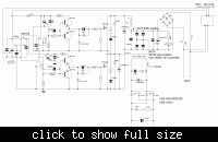
seems to be drawn as a step up transformer...
sorry, it is my mistake, indeed this a step down 1:4 transformer (ferrite core is taken from faulty 220>12V 300W AC-AC high frequency converter), so output voltage close to 36V.
L1 and L2 can be explained what they are and do
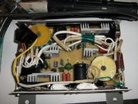
This is simply several whorls around signal wire, connected on local "minus" line. On my observations this reduces level of the hindrances when functioning the converter, and accordingly reduces separation of the heat on RC chains. That like ferrite tube, but sometimes better.
there seems no variable control of the current, is it not needed for that purpose ? (welding Cu wires and thermocouple)
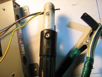
Yes, in general, but certain current regulation is present , by the way of change the length of graphite electrode.
would that work for welding copper wires to battery terminals ?
No, it does not be fit for such use.


all of u should have a look at this welder (upto 100amps)
Else interesting project - a welding device with management on ATMega8.
http://www.electrik.org/forum/index.php?showtopic=25898
Archive with scheme, .hex, etc. at the and of first message.
http://www.electrik.org/forum/index.php?act=attach&type=post&id=15220
 
Last edited:
well guys i find the atmega welder really complex. the link which i have given is a very simple welder based on uc3844 it has current feedback and again here they are ( for those who havent noticed it). :


Welding inverter 100A ------ this link is original and shows voltage and current feedback.
Svec invertor do 100A ---- this link is the same welder but the author has provided a pcb in eagle. the author has copied from the above link and additionally provided the pcb for the welder.

the welder is also used as a power supply. seee these links --- Regulovateln zdroj 3-60V / 30A
Regulovateln zdroj 3-60V 40A
 
Max pulsed current for IRFP460 - 80A against 220A IRG4PC50. So one IGBT changes three MOSFET-s ).
But if limit pulsed current, i think that possible use even IRF740. May be if installed them in redouble amount.
 

Just one note:

I see 20V. For welding you need at least 50V OV for rutilen or should I say 70 OV for basic coatic electrode, 24V at load for stick welding (SMAW/MMA) - say 20V ok.

You should increase OV. You will get sticked electrode very often - hard to start arc.

If you make HF MMA/SMAW you can use celulose electrode, aluminium electrode,...

For TIG 20V is ok but need HF its different story.


My personal opinion : It is not worth to build it, there is lots of low cost inverter comercial products in market, with exception if you whant to learn or make some production of them. Just metal case for DIY project cost a lots, and other parts....winding trafo....


Here is one circuit, its reliable and checked VARIN 1700, device from shop :
 

Attachments

  • VARIN1700 Schematic.pdf
    255.5 KB · Views: 968
Last edited:

Max pulsed current for IRFP460 - 80A against 220A IRG4PC50. So one IGBT changes three MOSFET-s ).
But if limit pulsed current, i think that possible use even IRF740. May be if installed them in redouble amount.


can i change directly the IGBT based welder scheme (IRG4pc50U) to mosfet irfp460? without any components modification.
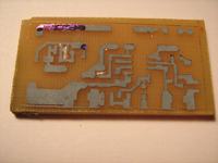
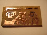
because i has built the PCB for IGBT welder scheme.
 

can i change directly the IGBT based welder scheme (IRG4pc50U) to mosfet irfp460?
If speech goes about device for wire welding, i think yes, you can. But i did not try that. Can be will however be necessary to put additional inductor on output. However my several years old device maded from two modules ir2153+2x irf740 hitherto works orderly.

In device for welding metallic construction one IRFP460 in shoulder it is not enough.

is that device work fine?
because irf740 has only 10A maximum current...
i saw your picture has no paralel mosfet to double the ampere capacity.
CMIIW
 

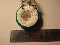
can i use this my DIY toroidal transformer?
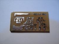
Picture004.jpg

Primary : 20 turns @ 2,5mmSq X 1 solid cooper
secondary: 6 turns @ 2,5mmSq X 6 solid cooper
toroid : 10X40mm cross section toroid (50mm diameter toroid)


One more,
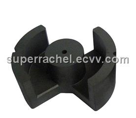
can i replace this shape transformer with same size toroid shape transformer?
China_large_power_Transformer_core_MnZn_Ferrite_core_PM_type20111141343193.jpg


replace with this one?

**broken link removed**

thanks in advance
 
Last edited:

is that device work fine?
yes, works either as earlier ).

your picture has no paralel mosfet to double the ampere capacity.
No parallel mosfet but two parallel converters.
can i use this my DIY toroidal transformer?
40mm core height?
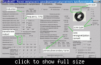
If that like Epcos N87 so results here is on picture got in the free program "Excellent IT".

But in any event, it is necessary will measure current consumption and core temperature when device be in idle time. Hope in the same way will not be forget to connect converter through lamp bulb (or something similar) at first time.
And else important circumstance - windings insulation must be an rack on attitude of the high temperature. For instance possible dress the fiberglass tube on wire of secondary windings.
can i replace this shape transformer with same size toroid shape transformer?
yes, unless air gap is required, and yellow ring usually not for transformer but for inductor.
 
  • Like
Reactions: wawanep

    wawanep

    Points: 2
    Helpful Answer Positive Rating

    Reza787315

    Points: 2
    Helpful Answer Positive Rating
oh shit..
I was wound my main transformer using yellow painted toroid..
Yellow paint major, with red paint at the front side of toroid. Can you help me to identify, what purpose this toroid?

Measurement of toroid:
50mm outside diameter
40mm inside diameter
cross section 45mm long x 10mm wide.
Why 45mm long? Because this 3 toroids stacked with glue.
 
Last edited:

Can you help me to identify
This is easy define by the means of Google >> IronPowder +yellow red >> Toroids - Micro Metals / Iron Powder

Аnd
50mm outside diameter
40mm inside diameter
cross section 45mm long x 10mm wide.
is overkill approximately in same degree as using 50A IGBT ).

It is wholly enough 40mm outside diameter, 10x14mm cross section. 40:10 primary : secondary.


because i has built the PCB for IGBT welder scheme
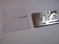
if thereabouts there is lazer printer and glossy photopaper for ink-jet printer possible to spend no more than one hour on PCB fabrication. But the photo paper needs to be inexpensive, because in this case thickness of glossy layer usually is more .
 
Last edited:

I think should change my toroid core, because yellow-red paint toroid doesn't suitable for 40khz application..

Next plan, i wish to find flyback television ferrite or toroid for TV deflection.

This project has spend my money near a price a new china inverter welder. Hahaha..
 

Hi deepone..
I was bought used ferrite transformer for $3.
The shape double U, cross section 14mm x 12mm. Is this enough?
 

shape double U, cross section 14mm x 12mm. Is this enough?
May be. Quite well else know core external sizes.
If material has a no covering, it is necessary cover it, for instance by using tacky paper tape applicable in building purpose.

ps.
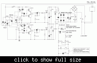
has corrected the scheme in a part of half-bridge capacitors capacity.
 
Last edited:

External size of my new ferrite is 60mm x 40mm. Fit for 24turns primary at 2,5mm square solid wire. 6turns secondary at 2,5mmSq x 6 solid wire.
 

Fit for 24turns primary at 2,5mm square solid wire. 6turns secondary at 2,5mmSq x 6 solid wire.
Sensibly will make primary from more fine wire 0,6x2 or 1x1,5 sq.mm.
For such ferrite possible will better 36:9.
 

Do you have transformer application? For calculate minimum ferrit size, maximum power deliver, and optimum primary and secondary turns or wire size.

Big thanks..
 

Status
Not open for further replies.

Part and Inventory Search

Welcome to EDABoard.com

Sponsor

Back
Top