Continue to Site

Welcome to EDAboard.com

Welcome to our site! EDAboard.com is an international Electronics Discussion Forum focused on EDA software, circuits, schematics, books, theory, papers, asic, pld, 8051, DSP, Network, RF, Analog Design, PCB, Service Manuals... and a whole lot more! To participate you need to register. Registration is free. Click here to register now.

Design tips for SG3525A...

Status
Not open for further replies.

powersys

Advanced Member level 1
Joined
Nov 29, 2005
Messages
439
Helped
3
Reputation
6
Reaction score
2
Trophy points
1,298
Activity points
4,981
sg3525a

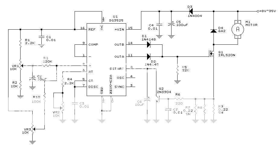
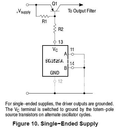
I wish to generate a PWM signal using SG3525A. I have donwloaded the datasheet but couldn't find a complete circuit to generate the PWM signal. If I'm not mistaken, SG3525A allows us to vary the frequency and duty-cycle of the PWM signal. Would someone pls share the idea or circuit schematic to perform the task? Thanks.
 

sg3525a circuit

Do you have this datasheet from On Semiconductor https://www.onsemi.com/pub/Collateral/SG3525A-D.PDF There is a test circuit to generate a pulse on page 5 of the datasheet document. With this controller, the timing resistors RT and CT determine the frequency of operation (oscillator frequency). The relationship between RT, CT and the frequency is given on Figure 3 on page 6. The duty ratio is determined by the error voltage from Error amp output when it is compared with the internal sawtooth. So the frequency is fixed once you pick RT and CT and the duty ratio adjusts to regulate the output voltage. How fast and how stable the regulation -- that depends on the compensation network.

By the way the UC3525A from Unitrode (now Texas Instruments) is similar if not identical to the SG part (I think SG stands for Silicon General, which I don't know is still around). Here's the link the the UC3525A datasheet https://focus.ti.com/lit/ds/symlink/uc3525a.pdf
I think there is also LT3525A which is from Linear Technology.

For an example of SG3525 in action look at Figures 2 and 9 of this page **broken link removed**

I hope that this helps you out.

Best regards,
v_c
 

sg3525a

Have a look at the schematic below ..

PWM range can be adjusted from 0-100%:
VR1: setting the minimum output voltage
VR3: setting the maximum output voltage

PWM frequency is 100HZ-5KHZ (adjustable):
VR2: setting the output frequency

If you don't need to control loads (motors, for example), components around Q1 and Q2 (current limit) can be omitted ..

Regards,
IanP
 

sg3525

IanP said:
PWM range can be adjusted from 0-100%:
VR1: setting the minimum output voltage
VR3: setting the maximum output voltage
Does the "0-100%" mean the duty-cycle of the PWM? If "0-100%" indicates the duty-cycle range, how come the maximum duty-cycle mentioned in the datasheet of UC3525A (downloaded from Unitrode) is around 49% only?

UC3525A.jpg
 

sg3525a circuits

The data sheet is correct for OutA and OutB, but in this example OutA and OutB are tied together ..

Regards,
IanP
 

pwm using sg3525a

IanP said:
The data sheet is correct for OutA and OutB, but in this example OutA and OutB are tied together ..
Sorry... but I still don't get your point yet. Would u pls advise how could the duty-cycle be extended to 100% when OutA and OutB are tied together? Thanks.
 

sg3524 test circuit

Take a look at the output signal form one channel, say, OutA --> picture below ..
Now, add OutB shifted by 180° ..
The resultant wave will have duty ratio from "almost" 0% to "almost "100% ..

Regards,
IanP
 

designing a controller using sg3525a

IanP said:
PWM frequency is 100HZ-5KHZ (adjustable):
VR2: setting the output frequency
PWM_SG3525.jpg


According to the schematic, RT=R4+VR2, CT=0.01uF.

When RT=2.2k, CT=0.01uF, from Figure 1, the Fosc = 50kHz (approx.)
When RT= 2.2k+10k=12.2k, CT=0.1uF, from Figure 2, Fosc = 10kHz (approx.)

Obviously, the results are different from the values (i.e. 100Hz and 5kHz) given in the article (Pulse Width Modulator DC Motor Controller). Do you agree with that? Pls advise.

By the way, are the diodes (D1 & D2) important to tie both OutA and OutB together? Can we tie OutA and OutB together without the diodes?

pwmFREQ_calculation_3.gif


pwmFREQ_calculation_4b.gif


Besides, what is the applicaition of the following circuit?

F10.jpg
 

www.onsemi.com/pub/cllateral sg3525a-d.pdf

You were right, the values of Rt and Ct on the schematic diagram were incorrect ..
They should be as follows:
RV2-->100kΩ
C3-->100nF
Ref: **broken link removed**

Fig.10 shows just another way of connecting external transistor to increase the output current ..

Regards,
IanP
 

sample sg3525a

IanP said:
You were right, the values of Rt and Ct on the schematic diagram were incorrect ..
They should be as follows:
RV2-->100kΩ
C3-->100nF
Ref: h**p://www.apogeekits.com/PDF_Files/Manual_K8004.pdf

Fig.10 shows just another way of connecting external transistor to increase the output current ..
Noted...

By the way, are the diodes (D1 & D2) important to tie both OutA and OutB together? Can we tie OutA and OutB together without the diodes?
 

sg3525a motor

As the outputs are "totem-pole" and because they work in opposite phases diodes prevent the outputs to work against each other ..

Regards,
IanP
 

    powersys

    Points: 2
    Helpful Answer Positive Rating
sg3525 circuit diagram

IanP said:
PWM range can be adjusted from 0-100%:
VR1: setting the minimum output voltage
VR3: setting the maximum output voltage
Based on the schematic in PWM_SG3525.jpg, why do we need TWO VRs to set the minimum and maximum duty cycle or output voltage? Pls Thanks.
 

sg3525a compensation

Of course, instead of 2 potentiometers you can have only one (see picture below) ..
Having two of them, however, give you additional flexibility to adjust minimum (or maximum) limit/offset ..

Regards,
IanP
 

sg3525a pwm circuit

It's look to me that there is more info in the datasheet of SG3524. I should have considered SG3524 at the beginning. However I have ordered SG3525...
 

sg3525 rt voltage

Can anybody tell me how can i get 50Hz friquency from 3525 means what will be its oscillator components.....
 

sg3525a schematic

hi,

can it be that the capacitor at C2 is actually defining the max voltage, time and the two potentiometers are there to adjust that timing.


just thinking fast :p:p:p:p:p
 

Status
Not open for further replies.

Similar threads

Part and Inventory Search

Welcome to EDABoard.com

Sponsor

Back
Top