Continue to Site

Welcome to EDAboard.com

Welcome to our site! EDAboard.com is an international Electronics Discussion Forum focused on EDA software, circuits, schematics, books, theory, papers, asic, pld, 8051, DSP, Network, RF, Analog Design, PCB, Service Manuals... and a whole lot more! To participate you need to register. Registration is free. Click here to register now.

Dynamic Threshold Compensation technique for UHF rectifiers

Status
Not open for further replies.

bwarlord01

Junior Member level 3
Joined
Sep 2, 2017
Messages
25
Helped
0
Reputation
0
Reaction score
0
Trophy points
1
Activity points
194
Hi, anyone know how the highlighted circuit below acts as a Dynamic Threshold Compensator for PMOS transistors? this is implemented in 65nm CMOS technology. And, i don't understand why the source terminal of the Diode-connected transistor (NMOS) is connected to the ground. Please i really need your help.

Below is the attached image of the circuit:
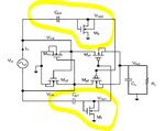
decoy.JPG
 

And, i don't understand why the source terminal of the Diode-connected transistor (NMOS) is connected to the ground.
It acts as bias resistor.

NMOS is a triple-well.

For PMOS on state, it feeds ground potential.
For PMOS off state, it feeds Vout potential.

However RF loss to substrate exists.
 

is it a good thing for a design in rectifier?
 

Status
Not open for further replies.

Similar threads

Part and Inventory Search

Welcome to EDABoard.com

Sponsor

Back
Top