Continue to Site

Welcome to EDAboard.com

Welcome to our site! EDAboard.com is an international Electronics Discussion Forum focused on EDA software, circuits, schematics, books, theory, papers, asic, pld, 8051, DSP, Network, RF, Analog Design, PCB, Service Manuals... and a whole lot more! To participate you need to register. Registration is free. Click here to register now.

[SOLVED] Variable voltage subractor

Status
Not open for further replies.

welove8051

Full Member level 6
Joined
Jul 16, 2009
Messages
357
Helped
51
Reputation
102
Reaction score
41
Trophy points
1,308
Location
india
Activity points
3,277
hi, what are the challenges/possibilities to design the below circuit.

V1 is a 12V battery source. r1 is power resistor with value less than 1 ohms(based on requirement). V2 is the electronic circuit (using FET or OPAMP etc) with its own operating supply. V2 is always less than V1 so current flows from V1 to V2 all the time. the operation of circuit is that V2 will create a opposing voltage to V1 so that the current flown in the circuit through V2 is given by (V1 - V2)/r1. V2 should have the ability to pass current in the range of 15A continuous current.

the hard part here is that the V2 power supply can source current only for its operation and hence the current flown in the circuit should be supplied by V1 and pass through r1 and V2 back to his ground.


sub.PNG


thanks.
 

Hi,

some issues:
* I don´t see the use of this circuit.
* Is V2 a linear circuit or a switching circuit?
* 12V battery voltage source: What chemistry? If Pb, then you should consider a voltage range of 11V...14.4V
* "based on requirement": What does this mean?
* "less than 1 Ohms": For sure you need less than 1 Ohms. Even with V1= 12V and V2=0V it is impossible to run 15A through 1 Ohms
* "continous current": Does this mean DC current? If you are tlaking about PWM´d current: you need to specify whether you mean 15A of RMS current or 15A of average current.

Then three statements that dont fit:
1) "V2 is the electronic circuit (using FET or OPAMP etc) with its own operating supply."
2) "that the V2 power supply can source current only for its operation"
3) "the circuit should be supplied by V1"
The third statement violates statement 1 and statement 2

Klaus
 

sorry, if my question was not clear.

* I don´t see the use of this circuit.
this circuit is used for a simulating application, where load current is determined by voltage(V2).

* Is V2 a linear circuit or a switching circuit?
linear circuit.

* 12V battery voltage source: What chemistry? If Pb, then you should consider a voltage range of 11V...14.4V
Pb.

* "based on requirement": What does this mean?
As per first post if current requirement is 15 amps, then if v2 = 2v then R1 will be 0.666 ohms.

* "less than 1 Ohms": For sure you need less than 1 Ohms. Even with V1= 12V and V2=0V it is impossible to run 15A through 1 Ohms
R1 is given as 1 ohms wrongly in the image. its value will change based on the current that flow through V2.

* "continous current": Does this mean DC current? If you are tlaking about PWM´d current: you need to specify whether you mean 15A of RMS current or 15A of average current.
DC current. this is the current flows from V1 because of resistor and V2.

Then three statements that dont fit:
1) "V2 is the electronic circuit (using FET or OPAMP etc) with its own operating supply."
V2 is not independent power supply. it is a circuit made of opamp or MOSFET based electronic components. maybe we call it as black box circuit. the operating/biasing voltage of this circuit is a separate voltage source not shown in above circuit diagram.


2) "that the V2 power supply can source current only for its operation"
with respect to above statement V2 is powered by separate power supply and current from this power supply only sources black box circuit.

3) "the circuit should be supplied by V1"
The third statement violates statement 1 and statement 2
this is the full statement "the current flown in the circuit should be supplied by V1 and pass through r1 and V2 back to his ground"

the part which i required clarification is what kind of circuit is "V2 or black box circuit" that can give a variable voltage and also sinks the resultant current in the order of amps through it.

please let me know the reply is clear.

thanks
 

Hi,

Are you sure you want 3 variable values:
V1: 11V ... 14.4V
R1: to set the desired current
V2: variable voltage

Now what value can you rely on?

Linear: This means a lot of power: 14.4V x 15A = 216W max.
Depending on the voltages across R1 and V2...for worst case each of them needs to be rated wor 216W power dissipation.

What is your setpoint value? Is it the voltage across V2 or is it the loop current?

****
I recommend to make one value fix. I recommend R1.
Let´s assume a voltage drop on wires and MOSFET (inside V2) of totally 1.0V... This means R1 should be less than 0.65 Ohms. --> use 0.47 Ohms. About 106W @ 15A !!!

The rest makes the regulation loop inside V2. More than 110W power dissipation!!!

Klaus
 

Are you sure you want 3 variable values:
V1: 11V ... 14.4V
R1: to set the desired current
V2: variable voltage
Now what value can you rely on?

No. that's why i gave voltage as 12 and resistance(fixed) value based on max current required. only V2 will be variable.


Linear: This means a lot of power: 14.4V x 15A = 216W max.
Depending on the voltages across R1 and V2...for worst case each of them needs to be rated wor 216W power dissipation.

actually over all current cycle will be 1 to 2 seconds. and peak current 15A will be in milli seconds.

What is your setpoint value? Is it the voltage across V2 or is it the loop current?

voltage across V2 which determines the loop current.


The rest makes the regulation loop inside V2.
this is where i am expecting clarification, like how come voltage regulation and current sink can be carried out.

i want to know how this voltage subtraction of V1 and V2 can be carried (like opamp based voltage subtraction), and making the large current flow in the circuit.


thanks
 
Last edited:

You didn't yet specify the intended behavior of V2, at least not in an comprehensible way. You sketched an independent voltage source in your schematic which is probably not right. According to your description, you want a controlled source.

Please specify the equation for V2 voltage.
 

hi, let me brief my question with updated picture.
sub1.PNG

U is a circuit made of "opamp/MOSFET" (not sure how the design will be) is operated by its own power supply Vsource. U is a variable voltage generator circuit , which is always less than E. the positive side of U faces E's positive so that the voltage get subtracted and resulting in a current flow determined by R and given by the formula (I = (E-U) / R).

Resistance R depends on maximum current requirement. for R= 1.2 ohms, my max current I will be 10A for U = 0, and 5A for u = 6V. the current will flow from E to U and not otherwise.

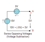
in simple i am trying to build the below circuit. the 5V voltage source has to be realized electronically.

sub2.PNG

i want to know how this voltage subtraction can be carried and making a large current flow in the circuit.


thanks
 

Hi,

voltage across V2 which determines the loop current.
Again my question: What is your target? (or: what is the target of your circuit?) Usually there is only one answer:
* Voltage V2 or
* loop current

***
As far as you tell: I don´t call V2 a voltage source. It´s just a variable voltage limiter ciruit or a variable current limiter circuit. (Depending on your answer above)
I don´t call it a "source" because it doesn´t deliver power, but it only consumes power.

****
In your picture of post#7 bottom:
You may replace the "5V" circuit with a 5V zener.

Klaus
 

Again my question: What is your target? (or: what is the target of your circuit?) Usually there is only one answer:
* Voltage V2 or
* loop current

my target is voltage. i just want to understand what will be the current flow path in the circuit.

how it will flow through V2, when it gives opposing voltage?

hope my question is clear.

thanks
 

Hi,

There is nothing special with your V2.
Even a resistor will show the same polarity like V2 in your schematic.

Any voltage limiting device acts like your V2...usually there is no need to supply your V2 circuit.....unless your V2 becomes so low that it can't drive the gate with enough voltage.

Klaus

ok. lets assume V1 =10V, i am putting LM317 regulator instead of V2 (or U) designed for 5v and R =1.2Ω. with respect to the formula (V1 - V2)/R I will be around 4A.

is LM317 is capable of sinking this current? if yes then how can we know the current sinking capability of the regulator. if no then what will happen to the regulator?


thanks.
 

A controlled source with I and V in the first or third quadrant (source is consuming power) can be imagined as a variable resistor. It can be also designed as DC/DC converter that retrieves the energy and delivers it to a load.

is LM317 is capable of sinking this current? if yes then how can we know the current sinking capability of the regulator. if no then what will happen to the regulator?
Need to consider both current and power rating. LM317 has rated current of 1 A (plus some margin). Trying to make it sink 4A drives it into internal current limit, the voltage drop increases to reduce the current. A stronger voltage regulator or LM317 with external transistor can do the job.
 
Hi,

is LM317 is capable of sinking this current?
Exactly this is the problem I tried to explain.
A LM317 is a power source unit, it is not made to sink current.
You need a voltage limiter - that may be passive - and you don't need a power source.

Maybe it helps if you look at current flow direction vs voltage.
A source current flow direction is opposite to the direction in your curcuit.

Klaus
 

A LM317 is a power source unit
Don't agree. It can be well used as power sink, the LM317 as such is always sinking power, the power in a voltage or current regulator setup is delivered by an additional source.

- - - Updated - - -

To make LM317 operate as a "voltage substractor" (= shunt voltage regulator), you need to invert it's feedback polarity. A dedicated shunt regulator IC would be an alternative.
 

Status
Not open for further replies.

Similar threads

Part and Inventory Search

Welcome to EDABoard.com

Sponsor

Back
Top