Continue to Site

Welcome to EDAboard.com

Welcome to our site! EDAboard.com is an international Electronics Discussion Forum focused on EDA software, circuits, schematics, books, theory, papers, asic, pld, 8051, DSP, Network, RF, Analog Design, PCB, Service Manuals... and a whole lot more! To participate you need to register. Registration is free. Click here to register now.

OP Amp amplifier circuit with output bias doesn't act as expected

Status
Not open for further replies.

pigtwo

Member level 4
Joined
Jul 16, 2015
Messages
70
Helped
0
Reputation
0
Reaction score
0
Trophy points
1,286
Activity points
2,771
Hello all,

I'm working on a small personal project where I want to take a signal from a microphone and do stuff with it. I'm trying to design a circuit to amplify the output from the microphone but I'm getting different results than I do from simulation. What I want to do is take a signal that can very from -200mV to 200mV and map this on to roughly 0V to 3.3V. I would like to do this without using a dual supply. I found this PDF from TI(https://www.ti.com/lit/an/sloa030a/sloa030a.pdf) that discusses this and gives a schematic that is what I need. Below is a screen shot of the schematic from the PDF.
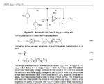
Case 3 Circuit.PNG

I did the calculations and came to the circuit shown below. As you can see the simulation shows this working as expected.
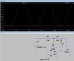
Case 3 Simulation.PNG

But I've built the actual circuit and it doesn't behave like this. What I get is similar but the bias(the b value in the equation) is way to small. It is too small by a factor of roughly the gain of the amplifier. For example with the equations provided by TI I expect that if I input 0V to the amplifier I should get 1.65V out. But I don't get that. On the output of the OP amp I get the voltage on the non-inverting input. So noticing this I just use two 10k resistors as a divider to get 1.65V on the non-inverting input and now it works as I want.

So I have the circuit working as I want but one of the main reasons I do these projects is to try to learn so I'm trying to figure out why I'm getting different results. If it's important the op-amp I'm using is TLV2775CN. I choose this somewhat arbitrarily so maybe I missed something with it. Does anyone know what might be causing this? I can provide more picture if needed.

Thank you!
 

Can you probe/plot the non-inverting node of your circuit in LT Spice?
 

Here is the plot of the non-inverting node.
non_inverting_node.PNG
 

The LT simulation assumes a AC signal source with no DC offset. Make sure in your practical circuit your source is also at zero DC offset. It won't take much mV offset to compress it up or down.
 

Hi,

The safe way for a single supplied amplifier is
* to generate VCC/2 at it's non inverting input
* and to connect a series capacitor at the input

The series capacitor makes the DC output independent of signal_source_DC_resistance.
And then you get VCC/2 at tge output, too.

Klaus
 

  • Like
Reactions: pigtwo

    pigtwo

    Points: 2
    Helpful Answer Positive Rating
The LT simulation assumes a AC signal source with no DC offset. Make sure in your practical circuit your source is also at zero DC offset. It won't take much mV offset to compress it up or down.

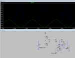
I checked and there doesn't appear to be a DC offset on the input signal but something with the input seems to be the problem. I'm ac coupling the input signal but I must not understand something because I changed the simulation to more accurately simulate my input signal and it now shows what I'm seeing. See the image below.
new_sim.PNG

I'm not very experienced with analog circuit design so maybe this is obvious but to me this doesn't make sense. Should the coupling capacitor block any DC? Or maybe it's a different effect that is causing this.

- - - Updated - - -

Hi,

The safe way for a single supplied amplifier is
* to generate VCC/2 at it's non inverting input
* and to connect a series capacitor at the input

The series capacitor makes the DC output independent of signal_source_DC_resistance.
And then you get VCC/2 at tge output, too.

Klaus

I think that's essentially what I'm doing except from what the equations TI provides you apply VCC/2 divided by (roughly)the gain of the amplifier to the non-inverting input.
 

Your R6 and R7 are doing nothing, remove them.
If you want the output to swing equally up and down then bias the (+) input at half the supply voltage (yours is biased at almost 0V) and use an input coupling capacitor. Oh, KlausST already said these things.
 

R6 and R7 were called for by the microphone manufacturer. Well actually it only calls for a single resistor but I'm assuming it's meant to bias it. So possibly I'm doing something wrong here. The microphone(or condenser, I don't know the difference between these if there is a difference) is ROM-2235P-HD-R.
microphone.PNG

I'm assuming the resistor is meant to bias it and since I didn't have 3V available I used a voltage divider. I was actually going to make another thread asking what the purpose of that resistor is and if a divider will work as well.

I want the output to swing between 0 and VCC but also to amplify the signal. If I apply the bias as you're recommending when I go to amplify the signal it will amplify the bias also. Which is how I came to the difference amplifier circuit.
 

Hi,

I think that's essentially what I'm doing except from what the equations TI provides you apply VCC/2 divided by (roughly)the gain of the amplifier to the non-inverting input
.

No. You don't give VCC/2 to non iverting input.
*****

The TI formula is
* for DC coupled input
* a signal source with very low DC resistance.
And they are correct as you see in your simulation.

The problem is that your signal source NOT does not have a low ohmic DC path, thetefore the output DC voltage is not correct.

To avoid all DC output problems --> use ALL of the recommendations of post#5.

Klaus
 

The Texas Instruments amplifier amplifies AC and DC because it does not have an input coupling capacitor that will prevent it from amplifying the DC bias.
Look up "electret microphone" in Google to see what it is and what it needs.
If you use a voltage divider to power the electret mic then it "loads down' the output level. Simply calculate a single resistor value with the supply voltage minus the voltage across the mic that you want and divided by the current (about 0.5mA) used by the mic (Ohm's Law).
Here is a good electret mic preamp (the minimum voltage for its TL071 audio opamp is about 7V):
 

Attachments

  • electret mic preamp.png
    electret mic preamp.png
    22.3 KB · Views: 137

@KlausST Ah I understand now. I misunderstood your post #5. I didn't notice the part about being independent of the sources' DC resistance. Thank you for the clarification.

@Audioguru Thank you for the explanation with the circuit example and correct name for that type of microphone. Just knowing the correct words to search for make it a lot easier to research. I think I mostly understand now but I still need to do a little research on my own.

One more quick question. I'm looking at the datasheet for the TL071 and there is a spec that kind of confuses me. See the screenshot below:
TL071_Datasheet.PNG

In table 6.1 it says the minimum difference between Vcc+ and Vcc is -0.3V and the maximum is 36V. To me this means it should be able to operate anywhere in between these values. But then in table 6.3 it says the minimum Vcc+ voltage is 5 volts. My first question is what is Vcc+ being compared to? There is no ground pin in the chip so is this saying Vcc+ must be 5v larger than Vcc-? If so that seems to contradict table 6.1. Then in the footnote of table 6.3 it says Vcc+ and Vcc- don't have to be the same magnitude unless their difference is between 10V and 30V. The problem I have with this is the magnitude part. Since the chip doesn't have a ground pin how could the chip even know if the magnitudes are equal or not? For example if I had Vcc+ = +5V and Vcc- = -5V this would be indistinguishable from Vcc+ = +10V and Vcc- = 0V.

I must be missing something here because it doesn't seem to make sense.

Thanks again!
 

Table 6.1 shows the maximum allowed supply voltages, not differences. The maximum allowed negative input voltage is wrongly called "minimum" and is 0.3V more negative than the negative supply voltage and the maximum allowed positive input voltage is 36V more positive than the negative supply voltage.
Who is the manufacturer and date of your datasheet because Texas Instruments invented the TL071 the their spec's are different to the ones you found.

The common mode voltage range is where the inputs work properly and is from 4V more positive than the negative supply up to the positive supply. The datasheet does not say that if an input voltage is within a few volts from the negative supply then the output of the opamp suddenly goes as high as it can go (opamp phase inversion problem).

The minimum supply says plus and minus 5V which is 10V in total. You can use -2V and +8V or 0V and +10V or anything in between. You can even use -10V and 0V if you want.
 

Ok that makes sense. I think this is the first time I've seen an op-amp that needs the input voltage to be that much higher than the negative rail so it kind of threw me off. I don't have much experience with op-amps but I usually saw it being a few tenths of a volt. Maybe this is because it's a JFET op-amp?

That's strange about the specs being different because that datasheet is from TI and it looks like it was updated July 2017. Here is a link to it: https://www.ti.com/lit/ds/symlink/tl071.pdf

I got it off the TI website for the part TL071.
 

Hi,

The bias voltage has nothing to do with Opamp type. It has nothing to do with common mode input voltage range.
It's the same with every Opamp.

With the capacitor in series with the input signal ... this simply causes the DC gain
* to be "0" (seen from the inverting input) this makes the DC output independent from DC signal input.
(This is what you need because you have an unknown DC resistance of your microphone)
* to be "1" (seen from the non inverting input).If you want maximum output swing you need the DC output to be VCC/2.
With gain = 1 it should be obvious that you need the same voltage at non inverting input --> VCC/2.

Klaus
 
  • Like
Reactions: pigtwo

    pigtwo

    Points: 2
    Helpful Answer Positive Rating
You want the output of an opamp to swing equally up and down. Then its (+) input is biased at half the supply voltage and an input coupling capacitor blocks DC. If the supply is dual polarity (plus and minus) then half the supply voltage is 0V.

If the opamp has a single positive supply and the (+) input is biased at a few tenths of a volt and has an input coupling capacitor then its output will idle at a few tenths of a voltage and it will amplify only the positive parts of the input signal which is a rectifier.

You showed a circuit with a single positive supply that had both inputs biased at a few tenths of a volt and had no input coupling capacitor. If the ratios of the resistors are correct then the output will idle at half the supply voltage and be able to swing equally up and down IF the input level is low and the gain is high. But if the input level is higher than a few tenths of a volt then the input will clip off the bottom of the waveform.
 

Just to clear things up a bit:

What I want to do is take a signal that can very from -200mV to 200mV and map this on to roughly 0V to 3.3V

1) What voltage do you have available to power the amp circuit? (3.3 V or 9 V)
2) You want to have the output to swing near 0 and 3.3 V, to feed to an ADC or something?
3) What is the frequency band you want to amplify? (speech only or ..)

It appears to me that an amp circuit with AC coupled output won't work for you, correct?

You want to have an AC coupled input (mic) and a resulting 0-3.3 Vpp output signal from what I can gather.
 

A microphone that you talk to or sing to has an output of about 10mV RMS which is +14.1mV to -14.1mV. Inside a drum or piano might produce +200mV to -200mV.

Many opamp outputs do not go down to 0V or up to the supply voltage unless they are rail-to-rail and have no load but an ADC is a load that will reduce the opamp maximum output swing.

You did not explain your map or its function. Maybe you want to record sound levels? The you should rectify the audio into varying DC so that no sound produces 0V, a low level sound produces a few hundred mV and a loud sound produces 3.3V.
 

@E-Design
1) I haven't actually created a circuit board yet so I'm flexible on what voltages could be available. Originally I wanted only a single +3.3V supply. But the more I'm learning about this the more I'm thinking it might just be easier to raise that up or do a dual supply.
2) Yes, that is the basic idea. I also wanted to do some filtering(other than AA filtering) before it goes to the ADC.
3) I originally planned for 20Hz-25kHz.

It appears to me that an amp circuit with AC coupled output won't work for you, correct?
I believe an AC output wouldn't work for me if I'm not using a dual supply. But I could be wrong about this. I assume I could always bias the output but without a dual supply I would think that the op-amp couldn't produce an AC output.

You want to have an AC coupled input (mic) and a resulting 0-3.3 Vpp output signal from what I can gather.
Yes, that is basically what I am trying to accomplish. Although I probably have not thought enough about this because the next step would be to bandpass filter afterwards. Which sort of seems to defeat the point of adding a DC bias. Not to mention without a dual supply I don't see how a bandpass filter(that doesn't include 0Hz in the pass band) can produce an AC signal. But maybe there is a way to bandpass filter then add a bias so the op amp doesn't clip the output.

@Audioguru
A microphone that you talk to or sing to has an output of about 10mV RMS which is +14.1mV to -14.1mV. Inside a drum or piano might produce +200mV to -200mV.
400mVpp then is probably too large. The way I got to that number is basically by loudly clapping next to the microphone which is probably not the best way to do this.

Many opamp outputs do not go down to 0V or up to the supply voltage unless they are rail-to-rail and have no load but an ADC is a load that will reduce the opamp maximum output swing.
Ah ok, that makes sense. I've always kind of assumed that op-amps could supply a lot of current before it would start to reduce the output. Which explains my confusion before.

You did not explain your map or its function. Maybe you want to record sound levels? The you should rectify the audio into varying DC so that no sound produces 0V, a low level sound produces a few hundred mV and a loud sound produces 3.3V.
That is basically correct. What I'm trying to make is basically one of those visual equalizer things. I'm not sure what they're called but it's like the colored bars that represent the frequency content of music or sound. So I wanted to take the output from a microphone, amplify it, bandpass filter it, then let an ADC sample it, and finally give that to an FPGA for some more processing.

So to answer your original question the reason for the mapping on to 0v to 3.3v was basically to amplify it and make it always positive. But I'm starting to think I should just use a dual supply. It's seems like this would be easier if I did. I'm not sure how I could bandpass filter this signal and still not have it go negative.
 

Hi,

Dual supply... biasing... depends on what ADC you use.
Some can handle negative input voltages, some can only process positive input voltages.
But in any cas a caoacitir at the Opamp output can adjust for the ADC DC nput bias. Like at the Opamp input.

It seems you want to build some kind of "simple" spectrum analyzer.

Consider to use a variable gain amplifier at signal input. Just for raw gain settings like : x 10, x1, x0.1

Consider to use an audio ADC. Should be no problem for an FPGA.

If you decide to control a lot of LEDs, then you need a good PCB layout to avoid that the switched LED current is fed back to the analog input signal.

Klaus
 

Status
Not open for further replies.

Similar threads

Part and Inventory Search

Welcome to EDABoard.com

Sponsor

Back
Top