Continue to Site

Welcome to EDAboard.com

Welcome to our site! EDAboard.com is an international Electronics Discussion Forum focused on EDA software, circuits, schematics, books, theory, papers, asic, pld, 8051, DSP, Network, RF, Analog Design, PCB, Service Manuals... and a whole lot more! To participate you need to register. Registration is free. Click here to register now.

Multi-stage rectifier

Status
Not open for further replies.

bwarlord01

Junior Member level 3
Joined
Sep 2, 2017
Messages
25
Helped
0
Reputation
0
Reaction score
0
Trophy points
1
Activity points
194
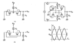
Hello, i am currently designing a Multi-stage rectifier with 0.3 Volts input, it consists of 6 stages of SVC rectifier. how come the output voltage exceeds its expected output value? the expected value is 1.8 Volts since (0.3Volts x 6 stages = 1.8V) although the output value should be <1.8V because of some voltage drops. How is it possible that it the rectifier i designed exceeds its expected value? is it a good thing? does it literally increase Power conversion efficiency?
 

it consists of 6 stages of SVC rectifier.
What do you mean by "SVC rectifier" ?

does it literally increase Power conversion efficiency?
You don't specify load condition.
So "Power conversion efficiency" is meaningless.
https://www.edaboard.com/showthread.php?t=360833#12

How is it possible that it the rectifier i designed exceeds its expected value?
You don't show operation frequency too.

Generally reverse current leakage is a primary cause.
 
Last edited:

SVC = self Vth cancellation

However unclear metric. 0.3V what? Vrms, Vpk?

For a meaningful question, we need source impedance, rectifier schematic, load impedance.
 

Attachments

  • 171125-200902.png
    171125-200902.png
    50.8 KB · Views: 53
Last edited:

I didn't want to claim that "SVC rectifier" is a commonly understood technical term, although Wikipedia disambiguation page isn't the only source of information in this regard.

I agree that it won't hurt the original poster to explain the term, even if it's frequently used in recent RF harvesting papers.
 

SVC = Self Vth Cancellation rectifier.

I am very sorry for the lack of information.
frequency = 2.4 GHz
load resistance = 1k ohms
load capacitance = 10pF
 

SVC = Self Vth Cancellation rectifier.
You don't clarify topology of rectifier at all.

CMOS Rectifier of https://www.edaboard.com/threads/351771/ is called as various names.

Kotani K., and Ito T., “High Efficiency CMOS Rectifier Circuit with Self-Vth-Cancellation And Power Regulation Functions for UHF RFIDs,” IEEE Asian Solid-State Circuits Conf. (ASSCC), pp. 119-122, 2007.

load resistance = 1k ohms
Iload=1.8mA, Pload=3.24mWatts=+5.1dBm
Even if Power conversion efficiency is 50%, Pin > +8dBm is required.
This Pin is fairly large.
 

Attachments

  • 171125-204304.png
    171125-204304.png
    18.1 KB · Views: 49
Last edited:

Status
Not open for further replies.

Similar threads

Part and Inventory Search

Welcome to EDABoard.com

Sponsor

Back
Top