Continue to Site

Welcome to EDAboard.com

Welcome to our site! EDAboard.com is an international Electronics Discussion Forum focused on EDA software, circuits, schematics, books, theory, papers, asic, pld, 8051, DSP, Network, RF, Analog Design, PCB, Service Manuals... and a whole lot more! To participate you need to register. Registration is free. Click here to register now.

Function Generator Output Source/Sink Current Max ?

Status
Not open for further replies.

vikash23

Full Member level 2
Joined
Jul 31, 2012
Messages
133
Helped
3
Reputation
6
Reaction score
3
Trophy points
1,298
Activity points
2,676
Hi,

I have a function generator AFG-2005

**broken link removed**

Can I please know how much it can source and sink in the output ?

I am looking around 100mA to source at the output.

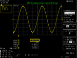
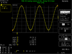
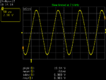
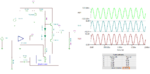
I would like to generate a sin wave of 7V pk-pk with 5KHz and to drive a load of 60mA - 70mA.

I dont prefer to use an opamp to the out put of sig gen as again i need to use a dual power supply for positive and negative voltage.
 

Measuring output into 35 Ohm load shows that 7V p-p giving 100mA peak current is achievable. i.e. +100mA when sine is at peak of +3.5V, 0mA when sine is at 0V, -100mA when sine is at -3.5V.

If you mean RMS current, then 90mA RMS is the maximum possible on my GW AFG-2105 at 5kHz and 7Vpp. (approx 25 Ohm load)
 
Last edited:
I have attached a image. Please have a look.

Can I able to drive this using this function generator.

What I came to know that the 50ohm internal resistor act as a voltage divider when connecting an external load resistor to the function generator,

Your reply shows the output load can be 35ohm.

But the load I am going to connect is 102ohm max.

Will I able to use my function generator for testing this load ?

test.jpg
 

That table shows voltage as 7V rms (19.8V p-p), not 7V peak to peak as you first stated.

I do not think the function generator can do the job, as it can only provide 20V p-p even with no load.

You are right that voltage decreases as load current increases.

I do not know how the function generator would behave with an inductive load, such as a motor, even if it could supply enough power. I would worry that motor back-EMF might cause damage to my function generator, though I have no idea whether that is true.

I think that you will need an amplifier of some kind.

With function generator set to maximum amplitude, 100 Ohm resistor load receives 47mA current with 5V rms across it (13.5V p-p).
 
Last edited:
Sorry for the wrong specification about the rms voltage.

I implemented a simple sine wave generator using NE555 timer IC but again the maximum input voltage is 18V and I require 20V. So I think I wont be able to use it.

I found something useful from TI.

https://www.ti.com/lit/an/slva696/slva696.pdf. Section 4.3 shows resolver excitation.

Will this make more complicated ?

Or Can I just use a power op-amp with dual power supply of (-ve and +ve) as shows in the figure and input a sine wave using NE555 timer that I have built already ?

pqzCW.png

I would like to make some thing quick and simple since it is a prototype.
 

Someone else will need to answer these questions. Not my area of expertise.
 

Any opamp circuit that uses a plus and minus power supply can use a single positive supply if its (+) input is biased at half the supply voltage and input and output coupling capacitors are used. The circuit you posted uses very many extra parts so that its DC output averages 0VDC. When you use an output coupling capacitor then the output of it will have any DC blocked by the capacitor so the extra parts are not needed.

A 555 does not produce a sinewave output. Why didn't you make a sinewave oscillator instead?


I generated a square wave output from 555 timer and changed to a sine wave using LC low pass filter

LTspice.jpg

Now what I need is to achieve the specification that I have mentioned in my earlier message.

7V rms, 5KHZ , can source 60mA.

Or can I use a function generator to generate 7Vrms and an opamp to increase the gain of the input signal. ?
 

You need some kind of power OP or audio power amp to drive the intended current. It's useful to provide quite a bit more current than presently required. I have e.g. TDA2030 to boost a function generator up to several 10 kHz.
 

Your second order LC filter poorly filters the signal from the 555 so it is not a pure sinewave. Actually, the output of the 555 is not a squarewave that has no even numbered harmonics, it is a rectangular waveform that has many even order harmonics and your simple filter does not remove the 2nd, 4th and 6th even order harmonics then the filtered waveform is distorted and has an average DC offset to it.

You can use a power opamp or an audio power amplifier IC with a function generator to provide the voltage and current you need.

Edit: Your simulation had a timebase frequency too low so the waveform is crammed together horizontally. I stretched it for it to be seen better:
 

Attachments

  • poor sinewave.png
    poor sinewave.png
    32.5 KB · Views: 169
Last edited:

    V

    Points: 2
    Helpful Answer Positive Rating
I am not sure exactly what you want to do. In another thread, you wanted a signal swing between zero and up. Here your simulation shows a bipolar output signal.

In any case, you can add a simple current booster to the op-amp signal as shown.

The distortion is about 1% THD. One of the factors causing this is that the 358 does not swing completely down to zero. It gets to about 50 -100 mV from zero. This can vary between different manufacturers.

It can also drive a 75 Ohm load with slightly more (1.3 % THD) distortion.
 

Attachments

  • opamp_boost.png
    opamp_boost.png
    51.4 KB · Views: 187
  • 75R_load.png
    75R_load.png
    25.7 KB · Views: 187

The LM358 produces crossover distortion and its poor slew rate does not allow high levels at 5kHz. The amplifier is missing negative feedback from its output.
 

The LM358 produces crossover distortion and its poor slew rate does not allow high levels at 5kHz.
Good point. Crossover distortion might be overcome in the circuit by class A bias, but the simulated slew rate is definitely beyond LM358 specifications (0.5 V/µs). Probably an incorrect OP model used.
 

I am not sure exactly what you want to do. In another thread, you wanted a signal swing between zero and up. Here your simulation shows a bipolar output signal.

In any case, you can add a simple current booster to the op-amp signal as shown.

The distortion is about 1% THD. One of the factors causing this is that the 358 does not swing completely down to zero. It gets to about 50 -100 mV from zero. This can vary between different manufacturers.

It can also drive a 75 Ohm load with slightly more (1.3 % THD) distortion.

I am trying to develop and simple circuit to test a resolver.

The specification of the resolver is mentioned in my above comments in the image.

I developed a circuit that generate a sine wave using a 555 timer and then realised the voltage pk to pk must me 20V and not 7V. (confused with rms and pk to pk voltage). Unfortunately my NE555 timer max input is 16V.

Thought I can use a function generator but then there will be voltage drop if I connect the load. Droped that plan.

Then I was planning to offset the signal from the 555 timer to zero and looking for a circuit that can do it. Now I am planning to develop a circuit with out zero offset.

Now trying to use a MOSFET to amplify the input signal from the function generator. Attached is the image. Still the output is clamped but working on different resistor and capacitor values .

MOSFET LTSPICE.jpg
 

Your simulation does not show where the waveform is coming from but I think it is at the 102 ohms resistor R22.
You do not "work at" a capacitor value, instead you simply calculate it with C= 1 divided by (2 x pi x freq x r)= 78uF for the output to be -3dB which is 0.707 times the input to the capacitor. Your 0.12uF is 650 times too small and it should be maybe 390uF for only a small 20Hz signal loss.

The problem with a Mosfet is that you do not know how much the one you buy conducts. Some conduct a lot and others conduct a little. You need an opamp with the Mosfet inside its negative feedback loop to control it or you can use a trimmer resistor and a temperature controlled oven. Wouldn't it be simpler to use an audio power amplifier that already has negative feedback built in?
 

The LM358 produces crossover distortion and its poor slew rate does not allow high levels at 5kHz. The amplifier is missing negative feedback from its output.

The crossover distortion can easily be controlled with light DC loading at the output of the 358. The 4.7k resistor is placed for this purpose. The value can be adjusted for lowest distortion.
https://www.youtube.com/watch?v=9a-F59UnEY8 Watch from the 17:00 mark on or at 27:00 for the actual fix
Another example:
https://www.youtube.com/watch?v=VgodYtiD_F0

but the simulated slew rate is definitely beyond LM358 specifications (0.5 V/µs). Probably an incorrect OP model used.
Most good specimens of the LM358 from reputable manufacturers can still perform well at 5 kHz in this circuit.

Using a single supply for this circuit, it performs better with just the local feedback. If you can add some negative supply, the distortion can be reduced an order of magnitude with global feedback.

I have bread-boarded this circuit configuration before using a 358 and will post some results later to illustrate.
----------------------------
With the supply slightly higher at 25 V, it gives a good 20 Vpp swing on the load.

With the DC load resistor (4.7k) reduced to 2.2k, the THD dropped down to 0.7%. Not bad at all, since the Agilent FG source produce about 0.05% of this.

At 6.5 kHz, the THD was up to 1% and climbing fast with an increase in frequency. At 7.5 kHz, it is severely slew-limited.

The GWInstek FG mentioned in the first post can't do better on distortion anyway.

Spec: (–55 dBc DC ~ 200kHz, Ampl > 0.1Vpp)
 

Attachments

  • lm358_dist.png
    lm358_dist.png
    26.9 KB · Views: 192
  • lm358_dist_20Vpp.png
    lm358_dist_20Vpp.png
    17.8 KB · Views: 172
  • lm358_dist_20Vpp_0.7THD.png
    lm358_dist_20Vpp_0.7THD.png
    21.8 KB · Views: 173
  • LM358_cct.jpg
    LM358_cct.jpg
    89.7 KB · Views: 188
  • slew_lim.png
    slew_lim.png
    14.3 KB · Views: 185
  • FFT.png
    FFT.png
    45.5 KB · Views: 183
  • -ve_supp.png
    -ve_supp.png
    57.6 KB · Views: 187
  • global_fb.png
    global_fb.png
    43.2 KB · Views: 170

Most good specimens of the LM358 from reputable manufacturers can still perform well at 5 kHz in this circuit.
You are right, 0.5V/µs refers to about 30 Vpp undistorted sine at 5 kHz.

I had tried to read the slew rate from the waveform diagram, obviously wrong.
 

The problems of crossover distortion and low slew rate are because the lousy old LM324 and LM358 are some of the first Low Current and Low Voltage opamps with inputs that work at 0V without a negative supply. I have used low current MC3317x opamps that also have the same low current, low voltage and inputs that work at 0V but they have no crossover distortion and have a much higher slew rate.
 

Obtaining 20 Vpp at 5 kHz is pushing it a bit.

We need about 0.6V/us to do this. Fortunately, it seems that the chip performs better than indicated on the data sheet. Using some knock-off parts, you may not be able to get this performance.

F := 5000 ;Vp:= 20
-----------------------------

SR:= (2*3.142*F*Vp)/1E6

SR=[628.4m] - 0.63V/µs required
 

Status
Not open for further replies.

Similar threads

Part and Inventory Search

Welcome to EDABoard.com

Sponsor

Back
Top