Continue to Site

Welcome to EDAboard.com

Welcome to our site! EDAboard.com is an international Electronics Discussion Forum focused on EDA software, circuits, schematics, books, theory, papers, asic, pld, 8051, DSP, Network, RF, Analog Design, PCB, Service Manuals... and a whole lot more! To participate you need to register. Registration is free. Click here to register now.

PIC24FJ interrupt 32 bit timer mode does not fire

Status
Not open for further replies.

Garyl

Full Member level 5
Joined
Mar 28, 2017
Messages
253
Helped
6
Reputation
12
Reaction score
7
Trophy points
18
Activity points
2,633
Hey,
I've triied to setup the 32 bit timer interrupt, according to the datasheet, but it's not starting.
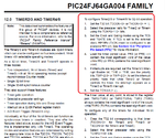
pic24fjtiemr32.png
The blinking and uart works, but the counter is not changing (nor the PR2/TMR2/PR3/TMR3).
What's missing?
Code:
int counter = 0;

void main() {
  char buff[64];
  ADPCFG = 0xFFFF;       // Configure AN pins as digital I/O
    AD1PCFG = 0x1C3F;               // Configure all pins as digital I/O
  TRISB = 0;             // Initialize PORTB as output

  LATB = 0;              // Set PORTB to zero

     RPOR1bits.RP2R=3; //Assign U1TX To Pin RP2 (pin 6)
     Delay_ms(100);
  UART1_Init(9600);               // Initialize UART module at 9600 bps
  Delay_ms(100);                  // Wait for UART module to stabilize

  UART1_Write_Text("Start");
  UART1_Write(13);
  UART1_Write(10);

   // TIMER 32 BIT!
   /*
   To configure Timer2/3 or Timer4/5 for 32-bit operation:
1. Set the T32 bit (T2CON<3> or T4CON<3> = 1).    */
  // SETBIT(T2CON,3);
  T2CON.T32 = 1;
/*
2. Select the prescaler ratio for Timer2 or Timer4
using the TCKPS<1:0> bits.
*/
    T2CON.TCKPS_0 = 0;
    T2CON.TCKPS_1 = 0;
/*
3. Set the Clock and Gating modes using the TCS
and TGATE bits. If TCS is set to the external
clock, RPINRx (TxCK) must be configured to an
available RPn pin. See Section 10.4 “Peripheral
Pin Select (PPS)” for more information.
*/
              /*
              bit 1 TCS: Timery Clock Source Select bit(1,2)
            1 = External clock from pin, TyCK (on the rising edge)
            0 = Internal clock (FOSC/2)
            */
   T2CON.TCS =  0;
            /*
            bit 6 TGATE: Timer1 Gated Time Accumulation Enable bit
          When TCS = 1:
          This bit is ignored.
          When TCS = 0:
          1 = Gated time accumulation is enabled
          0 = Gated time accumulation is disabled
          */
     T2CON.TGATE = 0;
/*
4. Load the timer period value. PR3 (or PR5) will
contain the most significant word of the value
while PR2 (or PR4) contains the least significant
word.       */
      PR3 = 0x00ff;
      PR2 = 0x00ff;
/*
5. If interrupts are required, set the Timer3/5 Interrupt
Enable bit, T3IE or T5IE; use the priority
bits, T3IP<2:0> or T5IP<2:0>, to set the interrupt
priority. Note that while Timer2 or Timer4
controls the timer, the interrupt appears as a
Timer3 or Timer5 interrupt.
*/
   IEC0.T3IE = 1;
   // TODO: set priority
   IPC2.T3IP_0 =  1;
   IPC2.T3IP_1 =  1;
   IPC2.T3IP_2 =  1;
/*
6. Set the TON bit (= 1).
*/
  T2CON.TON = 1;
         
  while(1) {
    sprintf(buff,"Cnt %i, PR3 %i, PR2 %i, TMR3 %i, TMR2 %i\n\r",counter, PR3, PR2, TMR3, TMR2);
    UART1_Write_Text(buff);
    LATB = ~LATB;        // Invert PORTB value
    Delay_ms(1000);
  }
}
void interrupt()
{
    counter++;
   IFS0.T3IF = 0;        //interrupt flag cleared
}
void Timer3Int() iv IVT_ADDR_T3INTERRUPT{// 0x1A Address in the interrupt vector table of timer1
    counter++;
     IFS0.T3IF = 0;        //interrupt flag cleared

}
 

How is the oscillator set up? What speed and what source?
Have you set the PRn registers correctly? They are 16-bit registers so the value you have set is 16,711,935. If you have a (say) 32MHz clock then you should get an interrupt about every second.
It is a bit hard to see your code in amongst all of those comments but the code you have presented looks OK. However there is a lot you have left out and that could be where the problem lies.
A couple of points that are not really related to your problem:
- find it a lot more readable wen you set all of the bits of a multi-bit field at the same time. For example, 'IPC2.T3IP = 7' is easier to understand than your equivalent. (Not sure the compiler you are using as the register field names are not those used for XC16 that I use - it may or may not allow for this style of coding.)
- I assume that you have set up the ISR correctly (again not the coding style I am used to)
- while you probably have done it as part of your attempts to get the interrupt to fire, I have rarely (i.e. only once) ever needed to play with the interrupt priorities. They are a very powerful tool but can lead you into all sorts of problems if you are not careful
- in your comment for the T3 ISR, you talk about Timer 1 and give the T1 ISR vector offset - however the code is for T3. This is a bit confusing.
- Not sure what the "void interrupt()" function is - again this may be something required by your compiler but does not fit the general PIC24 way fo doing things.
Susan
 

Entire circuit is tested in Proteus and code is written in mikroC.

Anyway, I don't know what to say, somehow everything (including the code from the post #1) started working today, suddenly...
I don't know, I didn't even restart the Proteus, it's just working now...
Maybe it was some internal Proteus issue and something wasn't reloaded, I don't know...
 

Status
Not open for further replies.

Similar threads

Part and Inventory Search

Welcome to EDABoard.com

Sponsor

Back
Top