Continue to Site

Welcome to EDAboard.com

Welcome to our site! EDAboard.com is an international Electronics Discussion Forum focused on EDA software, circuits, schematics, books, theory, papers, asic, pld, 8051, DSP, Network, RF, Analog Design, PCB, Service Manuals... and a whole lot more! To participate you need to register. Registration is free. Click here to register now.

Current limited LED and Difference between two types of capacitor

Status
Not open for further replies.
Because you will not be able to see the high frequency modulation of the LEDs, you need to first filter out all med and high frequency and keep only the low frequency components for the LED modulation. Use a low pass filter that cuts off all frequencies above 100Hz. Drive the LEDs via a transistor (or a MOSFET) and bias the base so that the LEDs just light up without any signal. Next connect your audio signal and have fun. You may also need an AGC stage before the transistor driver.
 
  • Like
Reactions: Vraj

    Vraj

    Points: 2
    Helpful Answer Positive Rating
We need to know what the signal comes from. An MP3 player, computer or radio tuner? Do you know its output impedance or can you post its schematic?
We also need to know the input impedance of your amplifiers.

The output impedance of most signal sources is 100 ohms or less and the input impedance of most amplifiers is 20k ohms or more. Then 200 amplifiers connected to a signal source produce a small drop in level with no increase of distortion.

Hi,
Hmm, ok my amplifiers are in case with speaker. It would difficult to open after arranging big stuff. Also it takes 4-5 hours for disassembly and reassembly. I will do in free time may be after 5 days.(adding 3rd amplifier) ;)
Thanks

- - - Updated - - -

Because you will not be able to see the high frequency modulation of the LEDs, you need to first filter out all med and high frequency and keep only the low frequency components for the LED modulation. Use a low pass filter that cuts off all frequencies above 100Hz. Drive the LEDs via a transistor (or a MOSFET) and bias the base so that the LEDs just light up without any signal. Next connect your audio signal and have fun. You may also need an AGC stage before the transistor driver.
Hi,

For AGC stage, uC is required?
Thanks
 

AGC is automatic gain control. You can look for a circuit in Google. Usually a Jfet is fed rectified audio. The Jfet cuts the level when the level is high.

If you do not use AGC then if you turn down the loudness the LEDs turn off. But AGC also might prevent the LEDs from turning on unless you adjust the LEDs to be turned on all the time.

Why do you think your amplified speakers must be taken apart? You parallel the inputs of the amplified speakers, not the outputs.
 

Hi,

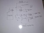
Here is the schematic.
I will find out more about AGC and add in to my design.

Thanks
 

Attachments

  • 1511674732149-390466780.jpg
    1511674732149-390466780.jpg
    497.5 KB · Views: 61

You need a small resistor in the filter; you have not shown the mosfet bias scheme. It may not work well unless the bias is correct (the mosfet is not a switch; it is working in the linear region and will need heat sinking)
 

The phone has an AC output that swings positive and negative and can drive 32 ohm earphones.
Your audio amplifiers probably have input coupling capacitors so that the AC input has DC blocked.
But the peak detectors have opamps with no part number, no voltage gain, no power supply and no input coupling capacitors so they might be rectifying the signal. Your Mosfet drivers will need voltage gain.

I would use single supply inverting opamps for the peak detectors and add voltage gain. Then they can simply drive emitter follower small power transistors (TIP31) to drive the LEDs without needing Mosfet drivers. An inverting opamp with a single supply and biased at 0V never has a damaging negative input when it does not have an input coupling capacitor and has an AC input that swings positive and negative.
 

Hi,

I made circuit. I need some suggestion for AGC. I made circuit with two opamp(ua741) one as gain amplifier and another as comparator. The O/P of comparator is directly driving mosfet(IRFZ44n) with 10k resistor on gate to source.

My speaker has two pcb circuits. One is audio receiver (sd, usb, fm, bluetooth,...) and second is amplifier board.
I drive another class D-amplifier by tapping o/p from that speaker's audio receiver circuit pcb.
I feel low power and distortion.
I want to use buffer.

Do anyone know which IC does 5.1 home theater use for driving 2 channel audio to 5.1 channel audio?

Thanks
 

I made circuit. I need some suggestion for AGC. I made circuit with two opamp(ua741) one as gain amplifier and another as comparator. The O/P of comparator is directly driving mosfet(IRFZ44n) with 10k resistor on gate to source.
Usually AGC is made with a Jfet with signal recification in an opamp circuit, look for it in Google.
The 741 opamp design is 50 years old and needs a fairly high dual polarity supply. A single supply modern opamp will use any supply voltage. An LM358 dual or LM324 quad opamp can be used to drive the diode feeding the RC peak detector and Mosfets.

Do you want to convert ordinary 2 channel stereo to surround sound 5.1? Then the surround sounds will be fake. I do not know of a converter IC.
 

Status
Not open for further replies.

Part and Inventory Search

Welcome to EDABoard.com

Sponsor

Back
Top