jasensio1
Newbie level 6
Hello everyone.
I´m having problems with switching mosfets.
Some of them appear to be damaged after some time, staying in ON state regardless control signal state.

The system is powered by a 7.2V lithium pack.
3V_2 rail is used to power an SD card.
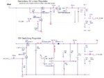
12V rail is used to power 2 current loop sensors. Each sensor is driven by the circuit below:

Q43B, Q44B and Q23B are the problematic parts.
Some of them fail after a few weeks, some of them after a few months, but always showing the same kind of failure, short between drain an source.
I haven´t been able to reproduce the issue. I hammered the circuit turning the transistors on and off thousands of times but could not get to any conclusions yet.
I detected high current transients when turning Q43B on, but as I said before, I couldn´t break it.
At the moment I only have theories about what is happening, like high dv/dt between drain and source or ringing at the mosfet gates, but I do not know what else to do to confirm where the problems are.
I know those pull-up and pull-down resistors values might be excessive, but I haven´t designed the system, so I can´t explain why those values where used.
This is MOSFET datasheet:
**broken link removed**
I would really appreciate any suggestion or comment, as I am stucked.
Thanks
I´m having problems with switching mosfets.
Some of them appear to be damaged after some time, staying in ON state regardless control signal state.

The system is powered by a 7.2V lithium pack.
3V_2 rail is used to power an SD card.
12V rail is used to power 2 current loop sensors. Each sensor is driven by the circuit below:
Q43B, Q44B and Q23B are the problematic parts.
Some of them fail after a few weeks, some of them after a few months, but always showing the same kind of failure, short between drain an source.
I haven´t been able to reproduce the issue. I hammered the circuit turning the transistors on and off thousands of times but could not get to any conclusions yet.
I detected high current transients when turning Q43B on, but as I said before, I couldn´t break it.
At the moment I only have theories about what is happening, like high dv/dt between drain and source or ringing at the mosfet gates, but I do not know what else to do to confirm where the problems are.
I know those pull-up and pull-down resistors values might be excessive, but I haven´t designed the system, so I can´t explain why those values where used.
This is MOSFET datasheet:
**broken link removed**
I would really appreciate any suggestion or comment, as I am stucked.
Thanks
