Continue to Site

Welcome to EDAboard.com

Welcome to our site! EDAboard.com is an international Electronics Discussion Forum focused on EDA software, circuits, schematics, books, theory, papers, asic, pld, 8051, DSP, Network, RF, Analog Design, PCB, Service Manuals... and a whole lot more! To participate you need to register. Registration is free. Click here to register now.

How to use field replaceable SMA connector for best data.

Status
Not open for further replies.

N.Narayanan

Junior Member level 3
Joined
Jan 24, 2013
Messages
27
Helped
9
Reputation
18
Reaction score
8
Trophy points
1,283
Location
India
Activity points
1,436
Hi all,
I am using SMA field replaceable connector. It has working but not as per the supplier spec.
The concern is centre PIN which is separate part. It has to be insert while testing the connector and DUT (solder with PCB).
So if anybody have experience on this type connector please help me that how to use this for best measurement.
Thanks in advance.
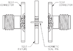
 

Forgot to mention the manufacturer and type specification.
 

Supplier is Dynawave. Connector type is 4 hole square flange field replaceable connector. We need to insert the separate centre PIN in centre of the connector to get the launch. There I am missing something.
 

Typical mount is like this

field_replacable.png

See also https://belfuse.com/resources/Produ...olutions/Johnson/pi-CCS-JOHN-142-1000-001.pdf for hermetic sealed pin details.
 

Hi, Thank you so much.
But already I have this information.
I am explaining my situation.
I separate centre PIN dia can be 11-16mil. I used 12mil. But Return loss data is only 15dB at 20GHz but specification is 20dB. So I am missing something.
Is there any common procedure to use field replaceable connectors?
 

But Return loss data is only 15dB at 20GHz but specification is 20dB.
Mentioning the exact problem from the start would be a good idea.

Looking at the supplied drawing, it's quite expectable that the high GHz return loss of the hermetic seal assembly is worse than of the basic SMA connector due to the center conductor discontinuity. You can check by modeling the geometry in an EM solver.

If you have a better specification for the assembly, are you sure that your design is complying with the manufacturer design in every detail? Did you check the return loss of the SMA cable plugs?
 
Yes. My test setup is good.
As you stated, discontinuity of centre PIN is a matter at high frequency (>5 GHz).
I came to enquire this because of this type connectors are supplying by all vendors. If so then there will be a root to get the best data.
 

Status
Not open for further replies.

Part and Inventory Search

Welcome to EDABoard.com

Sponsor

Back
Top