Continue to Site

Welcome to EDAboard.com

Welcome to our site! EDAboard.com is an international Electronics Discussion Forum focused on EDA software, circuits, schematics, books, theory, papers, asic, pld, 8051, DSP, Network, RF, Analog Design, PCB, Service Manuals... and a whole lot more! To participate you need to register. Registration is free. Click here to register now.

Input related tone appears in an ideal ADC

Status
Not open for further replies.

geppetto

Newbie level 3
Joined
Nov 19, 2017
Messages
3
Helped
0
Reputation
0
Reaction score
0
Trophy points
1
Activity points
30
Input related tones in an ideal ADC

Hi everyone.

I was trying to build an ideal 3-bit ADC model using MATLAB simulink.

However when I increased the number of points, I found input related tones appeared in the spectrum as below.

(2^18 point FFT, Sampling frequency = 200M, Input frequency = 20M with coherent sampling condition is satisfied)

Of course those amplitudes are well below the target SNDR. (ENOB is calculated as nearly 3-bit)

It may not be a problem but when it is over-sampled, these tones will limit the achievable ENOB.

I also checked with the cadence using ideal 3-bit veriloga codes but the results are exactly same.

Can anyone help me to understand why these tones are appeared?
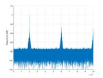
fft_ideal3bit.jpg
 
Last edited:

Guess your input signal isn't purely sinusoidal. These are odd-numbered overtones, indicating sort of square-wave-alike input. Pre-amplifier clipping?
 

Hi,

The duration of your measurement is 2^18 /200MHz = 1.31072ms
One cycle of your 20MHz signal is 50ns.

--> there is no integer fit of your signal within your measurement window
--> you need to perform a windowing function (hanning, hamming...) before you run the FFT to get plausible results.

Klaus


Thanks for your reply :)

The applied input frequency is chosen as 19.996xx MHz to satisfy the coherent sampling condition and the hann window was applied.
 

Thanks for the reply erikl,

In the figure above, those tones look like the odd order harmonics however the locations are varying with the input frequency. (maybe I should chose some other example)

In some cases (some other input frequencies), tones appear on non odd order harmonic locations and even at dc. So I was guessing signal folding or some other issues.

The sine wave is generated by sine function (MATLAB) and vsin(cadence) and ofcourse there were no preamps.
 

Status
Not open for further replies.

Part and Inventory Search

Welcome to EDABoard.com

Sponsor

Back
Top