Continue to Site

Welcome to EDAboard.com

Welcome to our site! EDAboard.com is an international Electronics Discussion Forum focused on EDA software, circuits, schematics, books, theory, papers, asic, pld, 8051, DSP, Network, RF, Analog Design, PCB, Service Manuals... and a whole lot more! To participate you need to register. Registration is free. Click here to register now.

Fly-by ddr3 termination value

Status
Not open for further replies.

asadi.siyavash

Member level 4
Joined
Feb 14, 2013
Messages
68
Helped
2
Reputation
4
Reaction score
2
Trophy points
1,288
Activity points
1,769
Hello,
I want to design FPGA board with 64 bit DDR3 interface (4 DDR3). I choose FLY-BY topology. I read many documents about DDR3. but I am confused because I didn't know how I can set the value of external resistor termination of address command and control. I saw many different value in many boards. some of them used 47ohm (e.g. ti-am5728 board) or 40.2ohm (e.g. Genesys 2) or 30ohm (e.g. micron TN-41-13 document). could someone tell me how we can set this parameter?

any help would be greatly appreciated.
Siyavash
 

The external resistor need to be matched with your traces impedance. DDR controller usually has some output impedance selection options to match to line too.

Ideally you have to start with match value and with PCB at hands can be necessary to adapt the value to better signal integrity.


Look these guidelines: https://www.nxp.com/files-static/32bit/doc/app_note/AN3940.pdf

Texas AM335x datasheets / userguides has good informations too.
 
Last edited:

The external resistor need to be matched with your traces impedance. DDR controller usually has some output impedance selection options to match to line too.

Ideally you have to start with match value and with PCB at hands can be necessary to adapt the value to better signal integrity.


Look these guidelines: https://www.nxp.com/files-static/32bit/doc/app_note/AN3940.pdf

Texas AM335x datasheets / userguides has good informations too.

Hi, thank you.
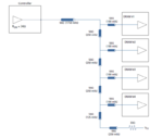
as you see in attached picture controller output impedance is 34ohm but line impedance is 50 ohm and termination impedance is 30ohm. could you please tell me how they choose these values?
zz.PNG
 

I read most of MICRON documents but I can't find what I need.
 

Look for an520 altera pdf. In this document you can see that DDR3 DIMM modules has 15 ohms series resistence and for reach 50 ohms =~ (15 + 34) of line impedance. Maybe the people that do these boards just copy values form DIMM without consider Rs.
 

I am trying to find the data sheet that explains this, did a board sometime this year with 2 DDR3 devices on board, that used 40R resistors I believe. Trying to find the data.
 

I think you mean Genesys 2 Kintex-7 FPGA Development Board
 

Status
Not open for further replies.

Similar threads

Part and Inventory Search

Welcome to EDABoard.com

Sponsor

Back
Top