Continue to Site

Welcome to EDAboard.com

Welcome to our site! EDAboard.com is an international Electronics Discussion Forum focused on EDA software, circuits, schematics, books, theory, papers, asic, pld, 8051, DSP, Network, RF, Analog Design, PCB, Service Manuals... and a whole lot more! To participate you need to register. Registration is free. Click here to register now.

Current sensing for controller

Status
Not open for further replies.

venkates2218

Full Member level 6
Joined
Sep 30, 2016
Messages
354
Helped
1
Reputation
2
Reaction score
1
Trophy points
1,298
Activity points
4,306
current sensor.png

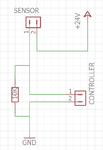
Please refer the image.
In my factory an gas sensor MICROSAFE MC-100 is used to sense the gas in chamber.Their is an controller in the chamber which control the gas flow based on the value in the gas sensor.
The sensor is operating in 24V DC power.According to this circuit which I observed is the controller sensing the current taken by the sensor and controlling the gas flow.

Operation of Gas sensor:
When the flow of gas increase the milliamps current taken by the sensor also increasing.At 10 PPM it will take 20mA.

My doubt is i need to sense the milliamps current by thee PIC controller to control the gas flow to the chamber.
I searched on Google but I can't get any circuit to sense the milli amps current.I need the range from 1mA to 20mA.
Please provide the circuit or some other way.
 

Re: current sensing for controller

Hi,

I assume you know Ohm´s law.

Now if I use your informations. 20mA.. and a 10k in series... this means 200V across the resistor.
--> there´s something wrong with your data.

***
You need a circuit to transform the sensor current into a measurable voltage.
--> the simplest circuit is to use the one that you show in your post.
The simple math you can do on your own.

Klaus
 

Re: current sensing for controller

You have to convert the current consumed by the sensor to the voltage range level within the microcontroller supply voltage.

As KlausST said, you should use simple Ohms law in order to calculate the resistance.

Since you are using the 24V supply, it is not a good design to interface the resistor logic directly with PIC. You should try to use some opto isolater or atleast some zener diodes there.
 

Re: current sensing for controller

Dont you require a ground for your sensor ?
 

Re: current sensing for controller

Dont you require a ground for your sensor ?

Yes,it need ground.But it given through the controller.

- - - Updated - - -

Hi,

I assume you know Ohm´s law.

Now if I use your informations. 20mA.. and a 10k in series... this means 200V across the resistor.
--> there´s something wrong with your data.

***
You need a circuit to transform the sensor current into a measurable voltage.
--> the simplest circuit is to use the one that you show in your post.
The simple math you can do on your own.

Klaus

i'm getting milliamps reading as negative value...
By this way how to do it..?
 

Re: current sensing for controller

Hi,

i'm getting milliamps reading as negative value...
By this way how to do it..?
Your answer doesn't relate to my post.

I currently can't see how you can get negative values.

If you are talking about software, then post your software.
If you are talking about mathematics, then show your calculations.
If you are talking about hardware, then show your hardware.

Klaus
 

Re: current sensing for controller

MUL_I.png

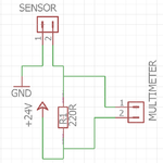
Please refer the image.
I connected 220R resistor across the positive supply and measured the DC voltage across the terminals of resistor.I can get positive voltage in multimeter.
I need to calculate the voltage in PIC controller.
To do this need to give only positive supply to analog pin of the PIC controller.

How to give analog input from this circuit.?
 

Re: current sensing for controller

Hi,

--> the simplest circuit is to use the one that you show in your post.
Why did you change the circuit now? It just makes things more difficult.

Klaus
 

Re: current sensing for controller

Hi,


Why did you change the circuit now? It just makes things more difficult.

Klaus

I searched so many circuits and got result in this circuit only.So only I changed the circuit.
 

Re: current sensing for controller

Hi,

You gave the circuit in post#1
I told you it´s the simplest solution.
Now you searched for other circuits.

Therefore I have to assume you don´t like a simple solution.

How difficult do you want it`?

Klaus
 

Re: current sensing for controller

Hi,

You gave the circuit in post#1
I told you it´s the simplest solution.
Now you searched for other circuits.

Therefore I have to assume you don´t like a simple solution.

How difficult do you want it`?

Klaus

I'm new to this one ok...
So i searched for the circuits,tutorials and got this circuit and get my output.
I don't have knowledge about this.So only i'm seeking helping from experts like you.

If you having solution for the first circuit itself means please give your advice i will flow that one.
 

Re: current sensing for controller

Hi,

I really don´t know what you want to hear.

In my eyes: The first circuit is the solution. Just calculate the correct resistor value. Simply using Ohm´s law. That´s it.
I think I already told you this in post#3.

Klaus
 

Re: current sensing for controller

Hi,

I really don´t know what you want to hear.

In my eyes: The first circuit is the solution. Just calculate the correct resistor value. Simply using Ohm´s law. That´s it.
I think I already told you this in post#3.

Klaus

Hi,
Thats ok Klaus.
The circuit shown in first post,which i observered from existing controller.It not having any schematics to understand the operation of the circuit.But now i'm going to read the value in PIC controller in that we can give only one wire to the RAO pin.

My doubt is how to connect this circuit to PIC controller for calculation operation.
 

Re: current sensing for controller

Hi,

how many possible connectins do you see?

* one wire of resistor is connected to GND
* microcontroller/ADC needs to use the same GND
* second wire of resistor connected to ADC input.

That´s it.

****
Idea for improvement:
For noise filtering I recommend to add some capacitor in parallel with your resistor.
Use RC low pass filter formula. You need to decide cutoff frequency.

Klaus
 

Re: current sensing for controller

Hi,

I agree with Klaus, circuit #1 is simple and easy to put together: for 1V ADC max input use a 50 ohm resistor (1V/0.020A = 50 ohms), for a 2V range ADC use a 100 ohm resistor. Whatever you do you should measure the resistor as accurately as possible, 47.5 ohms or 52.5 ohms (5% tolerance) will affect the precision of the readings, even 1% tolerance will have a little effect on the accuracy - 49 ohms gets 980mV at 20mA. You microcontroller experts will be able to write a little code to accommodate resistor value errors I suppose.
 

Status
Not open for further replies.

Similar threads

Part and Inventory Search

Welcome to EDABoard.com

Sponsor

Back
Top