michael 1978
Advanced Member level 4
hello
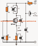
can somebody explain me, how does work capacitor between emitter and collector? and all circuit if its possible

[from imgur. com/a /fcJ5w]
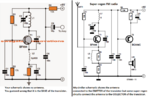
can somebody explain me, how does work capacitor between emitter and collector? and all circuit if its possible
[from imgur. com/a /fcJ5w]
Last edited by a moderator: