frankrose
Advanced Member level 3
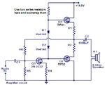
See the theory part:I disagree, a capacitive voltage divider does not matter. The capacitor between the collector and emitter simply provides positive feedback so that oscillation can happen.
Also, the transistor collector does not have "negative resistance".
https://en.wikipedia.org/wiki/Colpitts_oscillator