Continue to Site

Welcome to EDAboard.com

Welcome to our site! EDAboard.com is an international Electronics Discussion Forum focused on EDA software, circuits, schematics, books, theory, papers, asic, pld, 8051, DSP, Network, RF, Analog Design, PCB, Service Manuals... and a whole lot more! To participate you need to register. Registration is free. Click here to register now.

Please help me simulate the HF RF preamp circuit

Status
Not open for further replies.

neazoi

Advanced Member level 6
Joined
Jan 5, 2008
Messages
4,119
Helped
13
Reputation
26
Reaction score
15
Trophy points
1,318
Location
Greece
Activity points
36,918
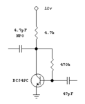
Hi I have built this little HF RF preamplifier.
Can you please simulate for me? I am interested in it's gain at 2MHz, 7MHz, 14MHz, and 28MHz
Note that it is the BC547C, the C version with a higher beta.

Can you propose of any higher gain HF amplifier circuit with one transistor only?
 

Attachments

  • Capture.PNG
    Capture.PNG
    2 KB · Views: 125

What is source and load impedance?

I have no idea, this is the preamp from this circuit **broken link removed**
I am not sute about the impedance of the crystal and the impedance of the antenna side.

I attach you a simulation I did, but I am new to ltspice and I may not have set some parameters correct.

Any estimation of impedances and help with the simulation, will be very valuable.

I am looking ways to make the RF preamp in this circuit to have higher gain at all HF bands. The use of another transistor? Altering of the passive components values?....
 

The BC549C isn't intended to be a low noise RF amplifier and as FvM has pointed out, the gain depends on what drives it and in particular what loads it. Consider the 4.7pF output capacitor alone has a reactance (think of it as series resistance) of almost 17K at 2MHz. Even at 28MHz, Xc is 1.2K.

I would think using a MMIC would be your easiest solution. They give lots of gain, are low noise and stable and best of all only need one load resistor and in/out coupling capacitors. They are quite old devices now but I used lots of MSA0135 in the past as general purpose gain blocks, they have a response from DC to > 1GHz with more than 20dB gain. The MSA0886 is inexpensive and will give you >30dB gain at 1Ghz and beyond with only 3dB noise figure.

Brian.
 
  • Like
Reactions: neazoi

    neazoi

    Points: 2
    Helpful Answer Positive Rating
The BC549C isn't intended to be a low noise RF amplifier and as FvM has pointed out, the gain depends on what drives it and in particular what loads it. Consider the 4.7pF output capacitor alone has a reactance (think of it as series resistance) of almost 17K at 2MHz. Even at 28MHz, Xc is 1.2K.

I would think using a MMIC would be your easiest solution. They give lots of gain, are low noise and stable and best of all only need one load resistor and in/out coupling capacitors. They are quite old devices now but I used lots of MSA0135 in the past as general purpose gain blocks, they have a response from DC to > 1GHz with more than 20dB gain. The MSA0886 is inexpensive and will give you >30dB gain at 1Ghz and beyond with only 3dB noise figure.

Brian.

Yes, if I change the load resistor from 1K to 100R the gain varied a lot. The problem is that in my circuit **broken link removed** I do not know what is the load the rf preamp sees.
So I can only do relative comparison between circuits.
In my circuit, the BC547C worked in practice very satisfactorily, I just need to see if the gain can be improved more.
Here is a variation of the RF preamp which gave lots of gain, compared to the original one. One factor is the increase in the coupling capacitors.
However, the output capacitor should not be very big, to avoid to load the crystal.

Do you know any good techniques to minimize crystal loading, whereas allowing good amount of power from the preamp to reach it (the single low value capacitor attenuates RF)?

I remember in the past, you have mentioned something about a transformer coupling, but I have lost this info now.
Have in mind that the circuit has to operate 2-30MHz.
 

Attachments

  • bjt.GIF
    bjt.GIF
    181.5 KB · Views: 107

That design has a lot of problems which cannot be overcome by changing values. The load we referred to isn't the collector resistor, it's the impedance after the coupling capacitor. Ignoring resonances, the 4.7pF coupling capacitor and the impedances after it form an attenuator which probably loses more signal than the transistor amplifies. The trouble with that design is the need to keep capacitance across the resonator to a minimum so you retain as much tuning range as possible so you can't increase the coupling.

In that design I don't think a transformer will help for the reasons you mentioned. True, it will help to match the impedance between the transistor and resonator but there is no way a single transformer will work effectively over that frequency range or work well with such a complex impedance as it's load.

If you want to try a MMIC you can just substitute one for the transistor, it will certainly provide much more RF gain but I'm not sure the AF output will work as well.

Brian.

I cannot find out why the circuit works, but it does and the end result is a quite sensitive receiver. I believe that the crystal operates also as a bpf, but surprisingly it is not narrow as expected, since I can receive SSB. A single crystal filter should be narrow and should not allow ssb reception.
It seems that the gain of the RF amplifier and the regenerative detector, overcomes the losses you refer to and the loss from the capacitive divider.
 

I think you misunderstand the function of the crystal, it isn't a filter, if it was you wouldn't hear anything that wasn't at it's resonant frequency. It sets the oscillator frequency and changing it's load capacitance 'pulls' the resonance slightly to give you some degree of tuning. The incoming signal amplitude modulates the oscillator and the non-linearity of the FET converts that back to the low frequency you hear.

Brian.
 
  • Like
Reactions: neazoi

    neazoi

    Points: 2
    Helpful Answer Positive Rating
The incoming signal amplitude modulates the oscillator and the non-linearity of the FET converts that back to the low frequency you hear.
Brian.
Can you please explain that in more detail Brian? How can the low level Rf input signal modulate the much more powerful oscillator, under which process does it happen?
The SSB is amplitude variations but also frequency variations, so under which mechanism does this modulation happen?
Also The suspicion that the crystal operates as a filter as well, came from the fact that this is the only point where the incoming signal input is applied, but also from the fact that it cannot led AF pass through it when reflex mode is on.

As I see it, to keep the coupling (and the capacitance) from the LO to the RF amp low, but at the same time to couple more signal from the RF amp to the LO, the only way I can think of, is to have more input signal from the antenna available. This means optimizing the RF amp, so that it can amplify more, or matching it better to the antenna, for a bigger input signal without changing the small coupling capacitor. What are your thoughts on this? Am I right or am I missing something?
 

I'll try to answer both posts together.

The circuit is a self oscillating mixer. If you removed the BC547 and all the components connected to it, you would have a JFET oscillator with a varicap to pull it slightly off frequency. By adding a tiny amount of received signal to it you get a mixing effect with the result being (Oscillator+signal frequency) and (oscillator-signal frequency) as products. The resulting amplitude also depends on the amplitudes of the two signals but as the oscillator has a fairly constant level, the result is the envelope of the received signal only.

The recovered signal(s) - don't forget this receives equally on both sides of the oscillator frequency, passes through the RF blocking components (see later) back to the base of the BC547 and then from it's collector to to AF output. The 4.7pF is a compromise, if you make it bigger you get more signal but reduce the tuning range, you want to keep anything in parallel with the varicap to a minimum so it has sole effect on the frequency. The value is in any case low enough that it doesn't pass audio frequencies.

Those blocking components, think of this: Suppose you have the output of a signal generator giving say 1V at 10MHz, how much is it reduced if you wire a 100nF capacitor and 3.3mH choke in series with it?

Regarding the best RF amp, you have conflicting requirements in that design. The BC547 stage has to carry the received frequency and also the recovered audio so it needs wide bandwidth, high gain and ideally low noise. It is almost impossible to satisfy all those requirements in one device. The BC547 is a poor choice for an RF amplifier anyway, it is intended for switching applications and has quite a high noise figure, especially when you consider the signal passes through it twice so you amplify the noise of the first pass on the second pass. Given the low level of the audio it would be better to use a good RF rated device in that position where the RF performance is more critical than audio.

Brian.
 
  • Like
Reactions: neazoi

    neazoi

    Points: 2
    Helpful Answer Positive Rating
I'll try to answer both posts together.

The circuit is a self oscillating mixer. If you removed the BC547 and all the components connected to it, you would have a JFET oscillator with a varicap to pull it slightly off frequency. By adding a tiny amount of received signal to it you get a mixing effect with the result being (Oscillator+signal frequency) and (oscillator-signal frequency) as products. The resulting amplitude also depends on the amplitudes of the two signals but as the oscillator has a fairly constant level, the result is the envelope of the received signal only.

The recovered signal(s) - don't forget this receives equally on both sides of the oscillator frequency, passes through the RF blocking components (see later) back to the base of the BC547 and then from it's collector to to AF output. The 4.7pF is a compromise, if you make it bigger you get more signal but reduce the tuning range, you want to keep anything in parallel with the varicap to a minimum so it has sole effect on the frequency. The value is in any case low enough that it doesn't pass audio frequencies.

Those blocking components, think of this: Suppose you have the output of a signal generator giving say 1V at 10MHz, how much is it reduced if you wire a 100nF capacitor and 3.3mH choke in series with it?

Regarding the best RF amp, you have conflicting requirements in that design. The BC547 stage has to carry the received frequency and also the recovered audio so it needs wide bandwidth, high gain and ideally low noise. It is almost impossible to satisfy all those requirements in one device. The BC547 is a poor choice for an RF amplifier anyway, it is intended for switching applications and has quite a high noise figure, especially when you consider the signal passes through it twice so you amplify the noise of the first pass on the second pass. Given the low level of the audio it would be better to use a good RF rated device in that position where the RF performance is more critical than audio.

Brian.

Thanks Brian!
I understand the thing about the detection. It is indeed a mixer as I thought, but the filtering is not provided by the crystal, but by the low value of coupling capacitor. To be honest, it is not clear to me why the crystal does not play a role on the AF blocking (to go let it go back to the detector) or that it does not have any filtering effect in the incoming RF signal.

I have tried 22nF shunt-to-ground capacitors instead for AC blocking, which did have an audible difference as well (LPF) but the bottom choke is needed to block RF to go back to the detector (as effective as it can be).

Regarding the use of BC547, it is actually the BC549C I am using **broken link removed** but the simulator did not have that transistor. If you can propose other such high beta (or greater) RF transistors, this would be of great interest to me to try them!
I am saying so, because to keep the coupling (and the capacitance) from the LO to the RF amp low, but at the same time to couple more signal from the RF amp to the LO, the only way I can think of without changing the coupling capacitor value, is to have more input signal from the antenna available. This means optimizing the RF amp, so that it can amplify more, or matching it better to the antenna, for a bigger input signal without changing the small coupling capacitor.
 

Status
Not open for further replies.

Part and Inventory Search

Welcome to EDABoard.com

Sponsor

Back
Top