Continue to Site

Welcome to EDAboard.com

Welcome to our site! EDAboard.com is an international Electronics Discussion Forum focused on EDA software, circuits, schematics, books, theory, papers, asic, pld, 8051, DSP, Network, RF, Analog Design, PCB, Service Manuals... and a whole lot more! To participate you need to register. Registration is free. Click here to register now.

LC network synthesis: 2nd example and questions

Status
Not open for further replies.

niki

Member level 4
Joined
Feb 20, 2002
Messages
70
Helped
20
Reputation
40
Reaction score
20
Trophy points
1,288
Location
Switzerland
Activity points
418
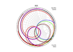
8 networks have 8 different input signals but all output signals are identical!
(see attachement)

Some informations about the networks:
All networks can be realized with positive values ​​of the elements
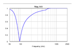
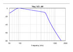
All networks have the same insertion loss (S21dB)
All networks have the same input return loss (S11dB)
All networks have the same output return loss (S22dB)

How is that possible?
What special requirements for the networks must be met?

Regards
Peter
 

Attachments

  • eda2.pdf
    676.5 KB · Views: 94

All networks have the same input return loss (S11dB)
Obviously, their frequency characteristics are different in "eda2.pdf".

Smply 8 networks have same frequency charateristics regarding frequency band of output signal.
 

In the attachment i've placed 3 examples with elements values. Therefore you can check the networks with simulations in the frequency and time domain.
Interesting frequency range: 20 kHz ... 1 MHz
Source signal (time domain): Square wave

The question still remains: how do the networks differ?
 

Attachments

  • eda_zwei.pdf
    364.9 KB · Views: 92

Your issue is very simple completely as same as your previous thread.
https://www.edaboard.com/showthread.php?t=372482#7

The question still remains: how do the networks differ?
Again, answer is https://www.edaboard.com/showthread.php?t=372889#2

Show us frequency characteristics of mag(S11) and phase(S11).

Then consider fourier expansion of source signal.

{S11, S12, S21, S22} is a unitary matrix, since networks are lossless.

So the followings are satisfied.

|S11|^2 + |S21|^2 = 1
|S12|^2 + |S22|^2 = 1

conj(S11)*S12 + conj(S21)*S22 = 0

From reciprocity, S12 = S21.

|S21|^2 = 1 - |S11|^2

|S11| = |S22|

There are two options for S11 and S22 in stop band.
One is open.
The other is short.

I assume S11=0 and S22=0 for pass band.
And |S11|=1 and |S22|=1 for stop band.

For lower stop band
(Case-1)
S11=1
S22=1

(Case-2)
S11=1
S22=-1

(Case-3)
S11=-1
S22=1

(Case-4)
S11=-1
S22=-1

These are true for upper stop band.
 
Last edited:

Show us frequency characteristics of mag(S11) and phase(S11).

Here are the plots of the eight networks
S11 (Smithchart)
Phase(S11)
Mag(S11)
Mag(S21)dB
 

Attachments

  • Mag_S11.png
    Mag_S11.png
    27.1 KB · Views: 77
  • Mag_S21_dB.png
    Mag_S21_dB.png
    31.5 KB · Views: 79
  • Phase_S11.png
    Phase_S11.png
    45.3 KB · Views: 80
  • S11.png
    S11.png
    130.9 KB · Views: 81

How should I relate the S11 plots to the claim in post #1?

Only the magnitude of S11 are identical (Return Loss), but the Phase(S11) are different for all networks.
This leads to the pretty curves in the smith chart!
And that is also the cause for different input signals in the time domain.
 

Thanks. I meaned to see different magnitudes in the Smith chart, but they aren't.
 

I wonder what's the conclusion from this interesting lesson about phase and magnitude of transfer functions.

If we e.g. design a chebychev or cauer filter, the specification sets s21 magnitude only. But the tabulated filter designs give a full set of complex poles and zeros, thus setting also s21 phase. Do I miss something?
 

I wonder what's the conclusion from this interesting lesson about phase and magnitude of transfer functions.
This is not interesting at all.
It is very easy things.

If we e.g. design a chebychev or cauer filter, the specification sets s21 magnitude only.
Wrong.
We start with polynomial, H(s)*H(-s), that is, zeros and pole.
Strictrly speaking, it is s11 not s21.
And relative phase is free to choose.

However we treat s21 instead of s11, since |S11|^2 + |S21|^2 = 1.

We can characterize reciprocal and lossless 2-port network by only s11.
 
Last edited:

I'm not particularly referring to reciprocal etc. networks, but to filter application. Implementation can be different, e.g. LC, active filter, digital. I don't particularly care for s11.

Your hint to relative phase answers the question for me. Although an offset Δφ(s21) is free to choose, dφ/dω(s21) isn't. This effectively fixes φ(s21) for a passive LC implementation, but not φ(s11).
 

Status
Not open for further replies.

Part and Inventory Search

Welcome to EDABoard.com

Sponsor

Back
Top