Continue to Site

Welcome to EDAboard.com

Welcome to our site! EDAboard.com is an international Electronics Discussion Forum focused on EDA software, circuits, schematics, books, theory, papers, asic, pld, 8051, DSP, Network, RF, Analog Design, PCB, Service Manuals... and a whole lot more! To participate you need to register. Registration is free. Click here to register now.

Parallel mosfet's as a dynamic load

Status
Not open for further replies.

Nizar_Ib

Member level 1
Joined
Nov 28, 2012
Messages
37
Helped
0
Reputation
0
Reaction score
0
Trophy points
1,286
Activity points
1,570
Hi,

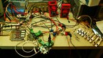
I'm building a loader to test Power Supplies, I'm using two parallel mosfet's to work as a dynamic load where can change the Vgs to control the current.
I have two mosfet's (P'N: IXTK200N10L2), which are connected parallely. see the circuit below:
Loader.JPG

I have some questions:
1) do I need to connect a resistor in the gate?
2) how can I ensure balanced current on both transistors?
3) because of the fact that I have a very small current on the gate, is it important which cable gauge I must put on the gate>source?
 

Hi,

1) it depends on the gate driving circuit. If it is fast enough it may cause ringing. Then a series resistor improves behaviour.

2) all depends on specifications. There will always be a deviation. How much is allowed at which current.
Usually MOSFETs don´t need a source resistor but you need a proper PCB layout to ensure good matching.

3) gate wiring should be as short as possible. The wire gauge doesn´t play much role. It is the series or loop impedance that causes problems. For more lengthy cabling I recommend shielded twiste pair.
One wire of the pair is the gat drive, the other is the source_sense. The driver has to take care about source_sense voltage.

Klaus
 

I don't know if it is necessary to match paralleled Mosfets operating in linear mode, but the only time I've done it I did match them with respect to Vgs(th).
That gave me some peace of mind, as I required that the circuit to be very reliable.

BTW, the application was identical to yours, an electronic load. And yes, it has been reliable.
 

If you pick the pair of MOSFET's that come as a matched pair in a single package you will have better matching otherwise you would have to manually check the matching of discrete components which is a little tedious and pick the right pair. Aother thing you can do is add a small resistor with enough wattage on the source of each MOSFET if you can afford the headroom since that would help them be more linear and give you better control of them. The amount of resistance that would be needed before it starts helping you would depend on the MOS you are using and the current put through them. Enough to make gm*R > 5 would be helpful.
 

I'm using 1m 28AWG gate wire without any resistor, I faced a strange issue, ringing on the voltage signal of the UUT, it happened randomly.
the UUT should supply 12V DC but I see sometimes 14V+, where the 2 Volts came from?
is a series resistor on the gate can fix the issue? which value should I use?
Thx.
 

It can come if the supply is has a ringing with the MOS gate load or if you have some inductance in the path which may be from your connections or even the parasitic inductance in the MOS gate terminal. Resistor may help. Larger the value better but to help choose the minimum value it's better to experiment and optimize using your setup.
 
Nothing been said about gate driver output impedance or speed. This definitely matters when selecting gate resistors. It's usually assumed that you need individual gate resistors to suppress RF oscillations.

If you can't select MOSFET with closely matched Vth, source resistors are the only practical way to achieve current matching.

What meant by "gate speed"? It is connected to the output of a regulator. It is manually controlled by me.
 

It is manually controlled by me.
So you say it's a purely static Vgs control without speed requirements. Means you should place gate resistors for parasitic oscillation suppression, e.g. 100 ohm each. And add current matching source resistors or select the MOSFET for closely matched threshold voltage.
 

Done this, but I used switched MOSFETs and fixed
(binary weighted) load resistors (SOIC FETs not being
great power dissipators).

The lashup in this picture has a fixed (baseline) load
of manual switches and resistors at far right, and the
pulsed MOSFET shunt load at far left. I used small 30V
NMOSFETs driven by a 1X:5X taper of 74HC14 gates
apiece, and PC post jumpers to select value there (if
you were real sophisticated you might build a parallel
word driven one, or even a SPI / I2C bus - whatever
fits your larger bench automation (if any) setup.
 

Attachments

  • Parallel_Spin4_resized.jpg
    Parallel_Spin4_resized.jpg
    439.2 KB · Views: 105

So you say it's a purely static Vgs control without speed requirements
the purpose of my circuit is to test the power supply with it's maximum current, so I change the Vgs to allow the maximum current of the power supply give me through the drain and source, for instance, I need to check a 30 Ampere of the UUT so I start to rise the Vgs slowly to get the 30 Ampere through Drain and Source.

e.g. 100 ohm each
why 100 ohm? is 10K ohm is good enough?
 

You need to beware that DMOS devices tend to be
good when "fully on" and "fully off", but tend to
concentrate linear power far from the heat sink
(i.e. in the "neck" of a VDMOS or channel of a
LDMOS) and can have a worse ruggedness there,
than in their normal switching states. I've blown
up many LDMOS devices trying to characterize the
load-line.

Much harder to fry a wirewound resistor. And switched
resistor schemes leave little doubt about the actual
current / resistance regardless of the goings-on,
while a linear driven gate has a lot of stability and
repeatability questions (offered above, and some yet
to be discovered when the hardware gets real).
 

why 100 ohm? is 10K ohm is good enough?
You don't tell much circuit details, so why should I suggest details without knowing a specfication?

100 ohm is good to suppress parasitic oscillations in the expectable range (SW to VHF). I still expect some kind of current controller with negative feedback from the shunt. Choosing the gate resistor too high may cause control loop stability problems.

More generally speaking, an electronic load with constant current is pretty standard and can be purchased of the shelf. No doubt that it can be implemented applying standard electronic design methods.
 

I've had trouble with commercial E-loads that try to present
constant current or constant impedance by feedback loop.
They interact sometimes with the DC_DC control loop and
make mysterious instabilities, that you get to go chase into
the weeds. For this reason I hand built my dynamic load jigs.

Besides this, E-loads can be pretty not-agile (compared to
the rise times that a converter customer might want to see
in a challenge case). If you want A/ms type rise times, fine.
A/uS, not likely. Maybe some, but you'd have to dig.

Nothing like tuning in load step response using an E-load,
and finding out that the loop values are all wrong on the
eval kit with just a 'scope and resistor load because you
were tweaking against a kooky piece of equipment.
 

how to protect the MOSFET from over current

Hi,

I have a very simple circuit, a mosfet connected to a power supplay (drain to source) and an external power supply to contol the Vgs.
I want tho check the power supply with 38A, how should I controll the Vgs?
can I supply a Vgs=5 instantly?
If not, what is the speed? I need to get steady state without damaging the FET

FET P/N: IXTK200N10L2.


Thanx.
 

Attachments

  • image.JPG
    image.JPG
    145.1 KB · Views: 86

Re: how to protect the MOSFET from over current

Hi,

What do yu really want?
Current limit to 38A? --> then use a constant current circuit with OPAMP and shunt. This is the recommended check for a power supply.
Keep MOSFET within SOA to avoid overload? --> use a microcontroller, measure U, I and calculate P
Prevent from overheat? --> limit power dissipation, use a temperature sensor and decrease current when close to critical temperature.

A simple fixed V_GS won´t protect your MOSFET.

Klaus
 

Since the load is unidirectional you might consider a
NPN power transistor or Darlington, as a (potentially)
more rugged solution. You will drop the same voltage
and power if controlled closed-loop, but the BJT
spreads power better internally, when operated
linear.

SOA charts tell the story, check them. And of course,
live up to their assumptions re case temp.
 

Status
Not open for further replies.

Similar threads

Part and Inventory Search

Welcome to EDABoard.com

Sponsor

Back
Top