Continue to Site

Welcome to EDAboard.com

Welcome to our site! EDAboard.com is an international Electronics Discussion Forum focused on EDA software, circuits, schematics, books, theory, papers, asic, pld, 8051, DSP, Network, RF, Analog Design, PCB, Service Manuals... and a whole lot more! To participate you need to register. Registration is free. Click here to register now.

Fully differential amplifier input protection

Status
Not open for further replies.

zan0

Newbie
Joined
Nov 8, 2017
Messages
5
Helped
0
Reputation
0
Reaction score
0
Trophy points
1
Location
Bordeaux
Activity points
47
Hi

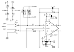
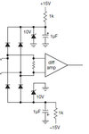
I was wondering , what is the best way for an input protection on a fully differential amplifier

i found this in AOE :

diode.jpg

I'm using a AD8138 from analog , powered by a +/-5V , i would like to clamp inputs within the rails supply

Is there a smarter way to do it ?

thx !
 

Hi,

The circuit is OK.
Why do you bother?

If you have special requirements on the circuit, then show us these specifications as values with units.

Btw: you say supply is +/-5V, but the circuit shows +/-10V.
If you ask for the "best way" you need to tell us what is "best" for you. Precision, cost, part count, size, noise, highest protection current...

Klaus


Thank you for your answer , the circuit shown above is just an exemple found in a book , my application will be powered by a +/- 5V

My worries were about the number of components ( 4 signal diode + 2 zener) , i think it may exist a package which include at least signals diodes but i don't know the number part , if you have an idea ?

i found also this component

https://m.littelfuse.com/~/media/electronics/datasheets/tvs_diode_arrays/littelfuse_tvs_diode_array_sp03_6_datasheet.pdf.pdf

but i 'm not sure it can works in differential mode ? what do you think ?
 

Hi,

the circuit shown above is just an exemple found in a book
... and the zeners are for reducing the OPAMP supply voltage to +/-10V and don´t have (much) to do with protection of the inputs.
I assume this is writen in the book....

4 signal diodes:
It´s the usual bridge rectifier circuit. --> There are low current rectifiers in a package as small as SOT23

Or just look for "signal line protection" devices. There are many. Some even have zeners inside.
The smallest I have are VBUS054B. 1.6 x 1.6 mm package for 4 signal lines and internal 5V zener. (Therefore not suitable for you)

There are double diodes in a package like
* schottky - for low voltage drop: BAT54S
* silicon - with especially low leakage current: BAV199
Do a search on your own.

Your component: I don´t think you need a 150A ligning source protection circuit.

Klaus
 

thanks angain

Here is my real circuit :

exp.png

suppose a 20VPP signal in inputs of AD8138 , it will be clamped at 5.6 V? (this is what i want )

is there a smarter way to do that ? , what about TVS bidirectional diode ?

thx
 

Hi,

Here is my real circuit :
A circuit without part values is only half of informations. (if ever)

suppose a 20VPP signal in inputs of AD8138 , it will be clamped at 5.6 V? (this is what i want )
No. It will cause smoke, maybe fire, because there is no current limiting device.

Why don´t you limit the voltage directly at the amplifier inputs (like in the circuit of post#1?)
Then the resistors will limit the current.

is there a smarter way to do that ? , what about TVS bidirectional diode ?
You need to calculate the voltage error caused by the leakage currents.
This determines if a TVS is good or not.
If you have the resistor values then you can calculate the power dissipation in the resistors and in the zeners.
If you expect fast transient signals: I recommend to add 10nF ceramics capacitors in parallel to the zeners.

Klaus
 

Hi,

No. It will cause smoke, maybe fire, because there is no current limiting device.

Why don´t you limit the voltage directly at the amplifier inputs (like in the circuit of post#1?)
Then the resistors will limit the current.

Klaus


I don't understand , it's almost the same input circuits !...:?:
 

Attachments

  • exp.png
    exp.png
    19.2 KB · Views: 125
  • diode.jpg
    diode.jpg
    10.3 KB · Views: 135

Hi,

I assume you cropped the picture of post#1 before you uploaded it.
--> show the complete schematic. Or give a link to the document where you took this picture from.

You say "almost". Then you know it isn't the same. I told you to connect the diodes directly at the amplifier input.
--> May I ask why you don't want to do this?

I told you that schematic without part value is not useful. But again you posted it without values.
You might have a good reson why you do this, but I don't understand.
I personally don't like to repeat myself....but without new information from your side I have to say:

Why don´t you limit the voltage directly at the amplifier inputs (like in the circuit of post#1?)
Then the resistors will limit the current.

If you can't imagine or can't calculate the input current that will flow when you apply 20V at an input, then use a simulation tool.
There are free ones, easy to use. Like LTspice.

Klaus
 

Hi,

You say "almost". Then you know it isn't the same. I told you to connect the diodes directly at the amplifier input.
--> May I ask why you don't want to do this?

Klaus

Hi ,

Can you show me with a drawing ?

thx
 

Designing input protection is impossible without specifying maxim input overvoltage and clamp current. Please supplement.
 

Hi,

Can you show me with a drawing ?
You already have it.
Look at the uncropped schematic of your post#1.

Klaus
 

Status
Not open for further replies.

Similar threads

Part and Inventory Search

Welcome to EDABoard.com

Sponsor

Back
Top