Continue to Site

Welcome to EDAboard.com

Welcome to our site! EDAboard.com is an international Electronics Discussion Forum focused on EDA software, circuits, schematics, books, theory, papers, asic, pld, 8051, DSP, Network, RF, Analog Design, PCB, Service Manuals... and a whole lot more! To participate you need to register. Registration is free. Click here to register now.

Feedback topology identification

Status
Not open for further replies.

CAMALEAO

Full Member level 4
Joined
Jul 29, 2016
Messages
201
Helped
2
Reputation
4
Reaction score
2
Trophy points
18
Activity points
1,868
Hi everyone, the title is self-explenatory.

I want to know if someone knows how to identify the kind of feedback is being applied on a circuit.

Regards.
 

What does "type of feedback" refer to?

Should we understand it e.g. according to the chapter "8.4 feedback configurations" in Gray, Hurst, Lewis, Meyer, Analysis and Design of Analog Integrated Circuits?

The text book distinguishes series-shunt, shunt-shunt, shunt-series and series-series configuration. A similar scheme in German literature distinguishes voltage/current controlled voltage and current feedback.
 

What does "type of feedback" refer to?
Should we understand it e.g. according to the chapter "8.4 feedback configurations" in Gray, Hurst, Lewis, Meyer, Analysis and Design of Analog Integrated Circuits?
The text book distinguishes series-shunt, shunt-shunt, shunt-series and series-series configuration. A similar scheme in German literature distinguishes voltage/current controlled voltage and current feedback.

Yes - and more than that: We have positive and negative feedback and resistive or capacitive or mixed feedback.
 

Sorry guys, apparently I was too vague.

Let me rephrase then :p

Basically, I want to know if someone can teach me or share how to identify which type of negative feedback amplifier structures, either resistive or capacitive. That is, identify series-shunt, shunt-shunt, shunt-series and series-series configuration in negative feedback amplifier.

I have difficulty in identifying what type of feedback amplifier I am presented to.

BR

Why don`t you show us the circuit topology you are interested in?
I am afraid, such a forum is not the right place to give you a complete lesson in feedback theory.
 
Does the "name" of feedback matter?
A common-emitter transistor can have an unbypassed emitter resistor or it can have a resistor from its collector to its base. They both create negative feedback and I have used them in designs hundreds of times without caring about what are their names.

Oh, sorry. I guess your teacher wants to know "if someone knows how to identify the kind of feedback is being applied on a circuit".
 

Does the "name" of feedback matter?
A common-emitter transistor can have an unbypassed emitter resistor or it can have a resistor from its collector to its base. They both create negative feedback and I have used them in designs hundreds of times without caring about what are their names.

Oh yes - For my opinion the name "matters". This is because knowing the topology of the feedback scheme is necessary for understanding the working principle and, in particular, the consequences of the various feedback schemes.
For example:
* Voltage-feedback increases the input resistance (opamp non-inverting, feedback with emitter resistor)
* Current feedback reduces the input resistance (opamp inverting, feedback with RB between collector and base)
 

Hi guys,

Thanks for all the replies.
It has nothing to do with the teacher.
I am trying to grasp this topic because I never understood it 100%. The first step is to know how to identify the feedback topology. As for an example, I have got the following examples:

1.PNG

2.jpg

3.jpg

View attachment 4.bmp

5.jpg

6.PNG

Can you guys give your view on which topology we have got here?
 

You can translate my voltage feedback and current feedback into series feedback or current feedback if your teacher wants it like that.
 

Thanks for the reply.

But how did you identified, for example, that in the third circuit you have current feedback?

In addition to this, if I may ask, what's the difference between the AC feedback and the DC feedback? What's the implication? How did you identify that?
 

But how did you identified, for example, that in the third circuit you have current feedback?
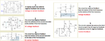
The negative feedback from the output cancels some of the input signal which reduces the input impedance.

In addition to this, if I may ask, what's the difference between the AC feedback and the DC feedback? What's the implication? How did you identify that?
There is a capacitor in series with the negative feedback resistor that passes AC but blocks DC. AC feedback affects only AC signals and has no effect on DC. DC feedback stabilized the DC operating condition so that hFE changes or temperature changes do not have much effect on the DC.
 

I see. However the feedback identification is not clear to me.

What's the benefit of AC feedback? In the case of the DC feedback it affects only the DC for example the op point. What about the AC? Affects the AC but how? What? What's the purpose of it?
 

What's the benefit of AC feedback? In the case of the DC feedback it affects only the DC for example the op point. What about the AC? Affects the AC but how? What? What's the purpose of it?

I suppose there's no particular benefit. It will be used if wideband (DC + AC) feedback isn't applicable for some reason or the designer didn't manage to find a respective solution.

The third circuit in post #9 is the only AC feedback circuit that has been presented in this thread. A DC+AC feedback version can probably achieve a lower component count, but may be a parameter e.g. voltage swing doesn't meet the requirements. We don't know the specifications, so we can't decide. We don't even know if the circuit serves a particular purpose or has been constructed for educational purposes.

A clear case where only AC feedback can be implemented is an amplifier with transformer coupling.
 

Didn't you learn about the benefits of AC negative feedback?
1) It reduces noise and distortion a lot.
2) It increases the bandwidth.
3) It can increase or decrease input impedance.
 

To be honest with you, I have learnt about feedback and not about DC or AC feedback.

Do you know any reference that makes this differentiation between thos e two types of feedback?

Still, the question was not answered.

How do you identify the type of feedback topology?
 

Status
Not open for further replies.

Similar threads

Part and Inventory Search

Welcome to EDABoard.com

Sponsor

Back
Top