Continue to Site

Welcome to EDAboard.com

Welcome to our site! EDAboard.com is an international Electronics Discussion Forum focused on EDA software, circuits, schematics, books, theory, papers, asic, pld, 8051, DSP, Network, RF, Analog Design, PCB, Service Manuals... and a whole lot more! To participate you need to register. Registration is free. Click here to register now.

[Moved]: Cmos 74hc14 conversion with frequency range

Status
Not open for further replies.

rob42

Newbie level 3
Joined
Nov 5, 2017
Messages
4
Helped
0
Reputation
0
Reaction score
0
Trophy points
1
Activity points
39
Hey guys, I would like to if you can assist me with my design. I designing a analog sinusoidal to digital format using the 74hc14. The input signal must go up to 500 kHz and the voltage met be limited. Can you please modify my circuit please. If this design cannot work, what design would you recommend?

Screen Shot 2017-11-05 at 1.11.43 PM.png
 

Re: Cmos 74hc14 conversion with frequency range

Hi,

I assume you need to move the capacitor to the location of the 27k resistor. (only one capacitor in the signal path needed)
This makes the HC14 input independent of signal DC level.

Then you need to install a pullup resistor (in addition to the 10k pulldown). calculate it´s value that it generates a DC bias voltage at the HC14 input that is in the middle of V_IH_typ and V_IL_typ.
--> read HC14 datasheet.

What is the lowest input frequency? --> this determines the capacitor value
What is input ignal voltage range in Vpp? --> you need this to check proper operation and abs_input_voltage_range limits.

Klaus
 

Re: Cmos 74hc14 conversion with frequency range

The lowest frequency is 0. If i anted to use another circuit without the hc14, schmitt trigger with transistors or comparators, can you suggest a circuit that will convert to sinusoidal ac sings to dc at the desired frequency range and voltage limited to around 0 - 3 volts.
 

Re: Cmos 74hc14 conversion with frequency range

Hi,

now it´s time for a full input signal specification:
* frequency range: 0...500kHz (this makes the circuit with series capacitor impossible)
* waveform: sinusoidal
* DC voltage range: ???
* AC voltage range in Vpp: ???

And tell us what you want to do with the digital signal.

My idea now: a comparator with small hysteresis.

Klaus
 

Re: Cmos 74hc14 conversion with frequency range

Dc voltage range is 3.1 volts
AC voltage range is 0 - 3.1 pk-pk
The digital will sent to a ADC and after to a cpld, so the desired frequency of input will be displayed.

If another design is better suited for my application rather than mines, you can change it.
 
Last edited by a moderator:

Re: Cmos 74hc14 conversion with frequency range

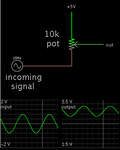
A potentiometer (resistor divider) can be used to add a desired DC component to your signal, whether the signal is AC or DC.

lift AC into DC range w potentiometer.png
 
  • Like
Reactions: rob42

    rob42

    Points: 2
    Helpful Answer Positive Rating
Re: Cmos 74hc14 conversion with frequency range

Hi,

Dc voltage range is 3.1 volts
AC voltage range is 0 - 3.1 pk-pk
The digital will sent to a ADC and after to a cpld, so the desired frequency of input will be displayed.

If another design is better suited for my application rather than mines, you can change it.

There's something wrong:
* I doubt there is 3.1V DC....please tell us where this signal is coming from
* with 0Vpp AC ... there is no signal at all! how do you decide to recognize it?

But the worst: The digital signal is sent to an ADC... What? An ADC has analog input and creates a digital signal.
What's the idea behind this?
An ADC is not useful for freqency measurement of a digital signal.

Klaus
 

[Moved]: Analog Sinusoidal Input to Digital Format

Hey,

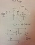
Can you guys please check my circuit design. I'm trying to design a schmitt trigger circuit that convert a analog to digital signal.

Frequency range: 0 - 500 kHz
Input voltage range: 0 - 3.1 v pk-pk
Resolution: 0.1 Hz

Also, the second circuit design is a protection circuit, where the relay will disconnect the circuit when the current exceeds 1A.

IMG_7995.jpg
 

Re: Analog Sinusoidal Input to Digital Format

Hi Rob,

You need to add the resistor values, and the actual transistor you plan to use, otherwise the experts here are looking at a vague sketch with no numbers to number-crunch ;).

If you have a little time to spare before making this circuit, getting familiar with a simulation tool will help to check a lot of things quickly, once you get over the more or less confusing and at times painful bump of understanding your simulator of choice. Look for LTspice when you get the chance. LT page says LT1017 has the spice model, and I would be beyond surprised if spice didn't contain the LM324.
 

Status
Not open for further replies.

Similar threads

Part and Inventory Search

Welcome to EDABoard.com

Sponsor

Back
Top