Continue to Site

Welcome to EDAboard.com

Welcome to our site! EDAboard.com is an international Electronics Discussion Forum focused on EDA software, circuits, schematics, books, theory, papers, asic, pld, 8051, DSP, Network, RF, Analog Design, PCB, Service Manuals... and a whole lot more! To participate you need to register. Registration is free. Click here to register now.

Texas Instrument's wrong Bulk cap formula

Status
Not open for further replies.

CataM

Advanced Member level 4
Joined
Dec 23, 2015
Messages
1,275
Helped
314
Reputation
628
Reaction score
312
Trophy points
83
Location
Madrid, Spain
Activity points
8,409
Hello everyone,

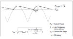
Calculating the bulk cap of a "C" filter for a full bridge rectifier (see picture), I get the conduction time "tc" as follows:
tc=arccos(Vmin/Vmax)/(2Πf)
Knowing that sin(Π/2-β)=cos(β), one gets the following:
tc=1/(4*f) - arcsin(Vmin/Vmax)/(2*Π*f)

Now inserting the above expression for "tc" which involves the "arcsin", one gets almost the same expression as at page 25, equation 3 of the TI's datasheet.

Using my calculations, I get 1/2Π * arcsin(Vmin/Vmax) while TI is showing 1/Π * arcsin(..). They are dividing by "pi" only.

Did I make any mistake ?

Any comment is appreciated.
 

Attachments

  • bulkCap.png
    bulkCap.png
    14.7 KB · Views: 105

Did I make any mistake ?

Yes.

Look at the graph you have attached. The peak to peak time corresponds to twice the line freq; that is how one 2 has disappeared.
 

I see that the peak to peak distance is Pi rad or 1/2*f seconds where f=50 Hz or 60 Hz, but the "tc" is the conduction angle divided by 2*Pi*f , not dived by 4*Pi*f. If you do so, you get wrong the "0.25" value and the division would be 4*Pi in front of the arcsin(..).

If you divde by Pi*f, then you get wrong the "0.25" value (you get "0") but you get correct the divided by "Pi" in front of the arcsin(..).
 

Checking the difference between those 2 formulas with a simple full wave rectifier with the following characteristics:
-Input source: sinusoidal with 220V RMS, 50 Hz
-Load: 96.7 ohms (1 kW for 220*sqrt(2) rectified)
-target ripple (Vmax-Vmin): 1 V

Using TI's formula (dividing the arcsin(..) only by "Pi"):
-C=46.6 mF
-resulted ripple: 0.59 V

Using my formula (dividing the arcsin(..) by 2*Pi):
-C=31.37 mF
-resulted ripple: 0.88 V

My formula is closer to the target value than TI's.. so I guess TI has it wrong.
 

the way to do it is with recursive (iterative) calculation in excel or matlab.
But maybe not bother, and just run the following ltspice simulation, which has a constant power load after the bridge rectifier........the const power load is your smps , say
Ill come back and attach it.
 

Attachments

  • Constant power load_386W.txt
    1.6 KB · Views: 67
  • Like
Reactions: CataM

    CataM

    Points: 2
    Helpful Answer Positive Rating
Thanks, yes ive seen similar formulae...the thing is, those formulae always require you to know the td or delta(t) value, and indeed you can get those from the scope...but before you have designed and built it, you cant do that.......so if you want to work it all out before you start your design, i believe you have to actually do an iterative calculation in say excel....and work though it like that , doing repeated (i.dt)/C = dv calculations.

...or of course, just use the simulator...i find the timescales for most projects are so fast, that the simulator is the usual way.....there's always the "oh ill come back and do the formal calculation later" attitude, ..but one never actually ends up getting time.
 

Status
Not open for further replies.

Similar threads

Part and Inventory Search

Welcome to EDABoard.com

Sponsor

Back
Top