Continue to Site

Welcome to EDAboard.com

Welcome to our site! EDAboard.com is an international Electronics Discussion Forum focused on EDA software, circuits, schematics, books, theory, papers, asic, pld, 8051, DSP, Network, RF, Analog Design, PCB, Service Manuals... and a whole lot more! To participate you need to register. Registration is free. Click here to register now.

[SOLVED] Fourier Series analysis and Time Domain analysis contradiction

Status
Not open for further replies.

CataM

Advanced Member level 4
Joined
Dec 23, 2015
Messages
1,275
Helped
314
Reputation
628
Reaction score
312
Trophy points
83
Location
Madrid, Spain
Activity points
8,409
Hello everyone,

Consider a RL circuit with R=0 ohms, making it a "L circuit" driven by a square wave with 0 average voltage. Initial condition of inductor's current= IC =0.
One can consider analyzing it by 2 methods:
1st Method: Fourier Series analysis
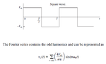
Take the Square Wave and find its Fourier series components. One gets that Square Wave with 0 average=0 + harmonics
Applying the Superposition Theorem, at DC, the voltage source is = 0 hence, the inductor's current is = to its initial condition = IC=0.

2nd Method: Time domain analysis
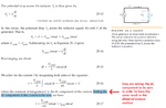
Current slope during positive cycle = - current slope during negative cycle = V/L
Since slopes are equal (their absolute value) and the time interval for both positive slope and negative slopes are equal, the current rises from its IC(=0) to some peak value and back to its IC(=0) value => Average current value ≠ 0.

So, one can see the contradiction between the 1st method result (Average current value=0) and the 2nd method (Average current value ≠ 0).

I know that in a practical case we will always have some resistance in the circuit, but my point is that well founded and widely used analysis techniques fail at simple cases !

Why am I saying this ? Because a full bridge converter has this issue if one models the xformer with its magnetizing inductance. I know all books in the full bridge converter says that the initial condition of the magnetizing current is -increment of magnetizing current/2 at t=0 in order to make the average =0, but that is not possible because initially the IC=0 and can not reach that value.
Obviously there is something that I am missing...
Am I making any mistake ?
 

Fourier has no respect for, comprehension of DC
(or stepwise DC) components of current.

RL circuits' current up/down is only equal when the
input duty cycle is 50% and the load has reached
V/2. Until that time the current in each phase and
the average are not settled. "Periodic steady state"
is reached after some time.

They may be widely used but you have to use them
for what they are capable of, not what you would
like them to be.
 
  • Like
Reactions: CataM

    CataM

    Points: 2
    Helpful Answer Positive Rating
Hi,

Your 2) analysis is wrong.
With your example both slopes are not equal. After the first full wave there will be a negative offset.
After some time it will become bigger until it reaches a certain level.

You may avoid this long time until it reaches steady state, if you start with 90° of the input signal.

Don't start with output = 0 and input +1, +1, -1, -1.... --> because the output will not return to zero after the full wave
But start with output = 0 and input +1, -1, -1, +1 ...... --> then the output will return to zero after each full wave

Klaus
 

The approach is not recommended:

Consider a RL circuit with R=0 ohms, making it a "L circuit" driven by a square wave with 0 average voltage

You should start with with a RL circuit with R=R1 and L=L1.

Then study the behaviour of the result when the R1 tends to zero.

As mentioned in post #3, you should also focus on the steady state behaviour, that is the result when t-->infinity.

If you want a transient analyssis, the methods can be different.
 

Your 2) analysis is wrong.
With your example both slopes are not equal. After the first full wave there will be a negative offset.
[..]
Don't start with output = 0 and input +1, +1, -1, -1.... --> because the output will not return to zero after the full wave
Let's see an example: L=1H, Vin= switches between 1 and -1 V with 1 Hz and 50% duty cycle. Initial condition for inductor current =0.
When Vin=1 => ipeak-IC=Vin/L*(D*Ts) <=> ipeak=0.5 A.
When Vin=-1 => iFINAL-0.5=Vin/L *(1-D)*Ts <=> iFINAL=0.5-0.5=0 A.
We are back to 0 amps again.So you can do this for forever and still get this. This means we reached steady state.

The approach is not recommended:

You should start with with a RL circuit with R=R1 and L=L1.

Then study the behaviour of the result when the R1 tends to zero.

As mentioned in post #3, you should also focus on the steady state behaviour, that is the result when t-->infinity.
The thing is that the steady state is reached, do not have to wait for more cycles.
 

The thing is that the steady state is reached, do not have to wait for more cycles.

With R is equal to zero, you have a time constant that is one over zero and with a square wave you will have singularities that you do not know how to handle.

You will have problems at the rising edge and the falling edge and the currents cannot be calculated.

When Vin=1 => ipeak-IC=Vin/L*(D*Ts) <=> ipeak=0.5 A.

Your calculation is WRONG. Please redo and recheck.

Fourier transformation DOES not work near poles or singularities
 
Last edited:

Hi,

Let's see an example:
Nice words. But why don´t you run a simulation?
See how it behaves. Initialized with zero volt, zero current. 1V, 1 Ohm, 1H.
--> it simply doesn´t return to zero after the first full wave... like expected.
RL_1.png

Klaus
 

I see some confusion: see the fourier expansion of a square wave (for few terms):

View attachment case2.pdf

Now use the superposition theorem: calculate the current for each sine wave and add the results. The XL is frequency dependent and therefore the results will be interesting...

- - - Updated - - -

Without loss of generality, we assume the frequency of the square wave as 1 and the L is also equal to 1. The reactance will be 2*pi*f*L = 2*pi*1, 2*pi*3, 2*pi*5, 2*pi*7.

The current (ignore the phase for the time being) will be 1/XL (assume the voltage to be 1 for the square wave)- the phase shift is const at all freq...

Let us plot the currents:
View attachment case3.pdf

This has R=0 and now you can work out what will happen with some value of R.
 

Attachments

  • case3.pdf
    22.3 KB · Views: 57
Last edited:

The thing is that the steady state is reached, do not have to wait for more cycles.
That's just an unfounded assumption. You are setting arbitrary initial conditions and hope that they belong to the steady state solution. Unfortunately they don't.
 

See how it behaves. Initialized with zero volt, zero current. 1V, 1 Ohm, 1H.
In post #1, I have said that we want to assume R=0. Making R=0 is the whole point of this thread.

I do understand as well your point from post #3 to start with 90º shift (+1,-1,-1,+1), which for the case R=0 would work, making a DC current value =0, but the point is that this must work starting at whatever point, even starting at +1,+1,-1,-1... which does not work by starting there and that is the point of this thread.

[...]
Without loss of generality, we assume the frequency of the square wave as 1 and the L is also equal to 1. The reactance will be 2*pi*f*L = 2*pi*1, 2*pi*3, 2*pi*5, 2*pi*7.

The current (ignore the phase for the time being) will be 1/XL (assume the voltage to be 1 for the square wave)- the phase shift is const at all freq...
[..]
You jumped to the well known conclusion of saying that the DC current is 0, and hence, only analyzing the harmonics, which by the way, is the same as I did in post #1, 1st method.

The thing that do not matches here is that we are constrained to the point we start in analyzing the circuit in the time domain because it gives 0 DC current (if you start like Klauss said : +1,-1,-1,+1) or different than 0 DC current (again, initial condition=0).
The circuit with zero resistance and zero initial condition for the inductance gives different results regarding the DC aspect of the current waveform, depending upon the method or point in time you start looking at it.

Last thing, the current through the inductor (AC-wise) is not 1/XL because the fourier series of the square wave does not have amplitude=1 for no harmonic in its series expansion. (see picture below)

- - - Updated - - -

That's just an unfounded assumption. You are setting arbitrary initial conditions and hope that they belong to the steady state solution. Unfortunately they don't.
I do not hope anything. I just do not care. I am thinking that if I start a circuit analysis at t=0, I assume all passive components are discharged because e.g. I have just bought them and the manufacturer gives them discharged.

If you start analyzing the current waveform of the magnetizing inductance for a Full bridge converter, before steady state is reached, you have to assume the xformer's inductance is demagnetized right? After some time, it will reach steady state.

Steady state is reached when i(some time)=i(some time + Ts). In the above example, some time=0 seconds, hence, I have arrived to the conclusion that i(0)=i(Ts) => reached steady state. If i(0) was different than i(Ts), I would have said, well, steady state is not reached yet and have to continue.
 

Attachments

  • squareWAVEfourierSeries.png
    squareWAVEfourierSeries.png
    15.7 KB · Views: 58
Last edited:

I think I know what is happening here.

The same problem happening here applies to an inductor (ideal) connected to a sinusoidal voltage source v(t)=V*sin(ωt).
If one solves the differential equation in order to find the current through the inductor, one gets this:
i(t)=V/ωL + IC - V/ωL *cos(ωt)=DC component + sinusoidal steady state, where IC=initial condition of the inductor current. [eq 0.]

If I set IC=0 (because I want so), one gets the current:
i(t)=i(t)=V/ωL - V/ωL *cos(ωt)=V/ωL*[1-cos(ωt)] >0 for all "t" !! [eq 1.]
What is happening here again ? This gives a different result than the sinusoidal steady state result gives. Now the sinusoidal steady state that we learned is not working ? If one solves using the sinusoidal steady state, he gets: i(t)=V/ωL *sin(ωt-Π/2) = - V/ωL *cos(ωt) [eq 2.]

Now [eq 1.] and [eq 2.] are very different !

Here comes a founded explanation which books do not say:
As c_mitra said and you guys and everyone says, there is no such case in reality, in reality we have some resistance. So start from general, and go towards the particular case.
So, solving the current for an RL circuit, one gets this:
i(t)=k*e^(-R*t/L)+V/Z *sin(ωt-φ) where φ=arctan(ωL/R) [eq 3.], and "k" must be found using the initial condition.

We do not care about finding "k" in [eq 3.] because in the steady state it is gone i.e. i(t)STEADY STATE=V/Z *sin(ωt-φ) [eq 4.]

Now, let's make R=0 and we have:
[eq 4.] --> i(t)STEADY STATE, R=0=V/ωL *sin(ωt-Π/2) same as [eq 2.], sinusoidal steady state.

In order to make this more general case be equal to the particular case when R=0, we need to make [eq 0.] be equal to [eq 2.], which leads to set "V/ωL + IC" in [eq 0.] to be zero (in other words, the DC current must be zero).

So the conclusion is as follows:
-One needs to set the Initial condition (IC)'s value in order to make the DC current = 0 for those "special cases" (particular) or in other words, to work in the boundary when R=0.(only when R=0)

-this is done also in order for the phasorial analysis to work. Otherwise, the phasorial analysis would not give the same result, comparing [eq 1.] and [eq 2.], unless as said, the IC is set to give zero DC current.

This is said also by the "Physics for Scientists and Engineers by Tipler" at page 1000 (see picture). Remeber you guys that in Physics clases, we were all thought that sinusoidal steady state formula for the Cap(ideal) and inductor(ideal), as is shown in Tipler.

So, the conclusion for the problem posted in post #1, the IC must be set in order to have 0 DC current. (I moved and talked about the same problem happenning in the sinusoidal regime because it is more widely covered, than a square wave .. I remembered the sinusoidal steady state and realized that there was the same "issue", and went from there because the sinusoidal regime is more widely covered..)

- - - Updated - - -
 

Attachments

  • TiplerPage1000.png
    TiplerPage1000.png
    67.6 KB · Views: 60
Last edited:

You jumped to the well known conclusion of saying that the DC current is 0, and hence, only analyzing the harmonics, which by the way, is the same as I did in post #1, 1st method.

No, I did not. The graph I showed has the fundamental (sine wave) plus harmonics. The graphs are (i) sine function (ii) sine + 3rd harmonic (iii) sine + 3rd + 5th harmonic (iv) sine + 3rd +5th + 7th harmonic. I have used the same function you have attached in your graph. Only thing I have put V =1 (that is without loss of generality).

Last thing, the current through the inductor (AC-wise) is not 1/XL because the fourier series of the square wave does not have amplitude=1 for no harmonic in its series expansion.

Current is calculated point by point; see the graph. It is called 1/XL because I have taken V in the square wave as 1; you just need to scale the Y axis for any other value.

In the same way, The four graphs are obtained by dividing the inst value of the voltage by the XL to get the inst current. This is ok because R=0.

Steady state is reached when i(some time)=i(some time + Ts).

Steady state is obtained when all monotone parts of the solution has died; steady state can have periodic solutions.

In the square wave plot you have attached, the voltage is periodic and square function AND is in a STEADY STATE. Just like a sine wave.

- - - Updated - - -

I presume that "they are setting the DC component..." is YOUR comment; this is wrong.

It is called boundary conditions; you must provide some initial values so that the integration constants can be determined. In this case, the boundary condition used is I=0 when VL(peak)=0. You need more complicated boundary conditions in other cases. In case of superconductors, this boundary condition may not be valid.

- - - Updated - - -

i(t)=V/ωL + IC - V/ωL *cos(ωt)=DC component + sinusoidal steady state, where IC=initial condition of the inductor current.

Something fishy; how did you get that?
 

Hi,

Now I see.
Yes, the pure "L" circuit behaves differently.
But you know this is a very theoretical case. Impossible to reach in reality.
The "L" circuit then needs a power supply that outputs a certain voltage with zero impedance, too.
Then the L acts as an integrator for the input voltage ( the value of L is somehow a gain constant) and the outputs it's value as current.

From the mathematical view you know when you integrate a function there is an unknown konstant.
In your circuit this is the "DC" value.

Now to fourier.
A fourier of the input square wave is:
0 DC
Your fundamental frequency with it's amplitude A
And the odd frequency overtones with their individual amplitude of A/f

Now running this through an integrator:
What does the integrator?
* It adds an unknown DC
* it generates a constant rising component according input average voltage
* It generates a phase shift to all input frequencies
* and it attenuates the frequencies with 1/f but multiplies every frequency with a constant value.

Give me some time to simulate this...

Klaus
 

Hi,

.. again reading through the thread..

you talk about superposition of DC.

If DC is 0 and you have finite gain, then the result is still 0
If DC is 0 and you have infinite gain (which is the case with a pure integrator = your ideal "L"), then the result is not defined.

***
fourier series of a square wave is:
...sin(x) + sin(3x)/3 + sin(5x)/5 + ....

fourier series of a triangle is:
...sin(x) - sin(3x)/3^2 + sin(5x)/5^2 - ....
the sign toggles because of the phase shift.
for a square wave the amplitude is attenuated 1/n ... now the integrater again attenuates it with 1/n therefore the 1/n^2 (where n = the order of the overtone = 1, 3, 5, ...)


Klaus

- - - Updated - - -

Hi,

.. again reading through the thread..

you talk about superposition of DC.

If DC is 0 and you have finite gain, then the result is still 0
If DC is 0 and you have infinite gain (which is the case with a pure integrator = your ideal "L"), then the result is not defined.

***
fourier series of a square wave is:
...sin(x) + sin(3x)/3 + sin(5x)/5 + ....

fourier series of a triangle is:
...sin(x) - sin(3x)/3^2 + sin(5x)/5^2 - ....
the sign toggles because of the phase shift.
for a square wave the amplitude is attenuated 1/n ... now the integrater again attenuates it with 1/n therefore the 1/n^2 (where n = the order of the overtone = 1, 3, 5, ...)


Klaus
 

Steady state is obtained when all monotone parts of the solution has died; steady state can have periodic solutions.

In the square wave plot you have attached, the voltage is periodic and square function AND is in a STEADY STATE. Just like a sine wave.
You have said the same as i(some time)=i(some time + Ts), just with another words.

I presume that "they are setting the DC component..." is YOUR comment; this is wrong.

It is called boundary conditions; you must provide some initial values so that the integration constants can be determined. In this case, the boundary condition used is I=0 when VL(peak)=0. You need more complicated boundary conditions in other cases. In case of superconductors, this boundary condition may not be valid.
Yes, it is my comment. The question here (and the point of this thread), is why do they set the DC component equal to zero ?
As I have shown in post #11, in [eq 0.], in order for the DC component to be zero, the IC (initial condition) must be equal to -V/ωL. That is something that is not straightforward to decide. I have also shown the reason they do that, which I repeat again: they do that in order to have consistent results with the sinusoidal steady state (which unfortunately, they do not say).


Something fishy; how did you get that?
v(t)=V*sin(ωt) => i(t)=IC + integral from "0" to "t" of v(t)/L

Just integrate and see.

From the mathematical view you know when you integrate a function there is an unknown konstant.
In your circuit this is the "DC" value.
Yes, the question is: Why everybody is setting that constant (DC value) to zero, leading to nontrivial initial conditions ? That is the point of this thread.

If DC is 0 and you have infinite gain (which is the case with a pure integrator = your ideal "L"), then the result is not defined.
Very true if and only if the voltage is applied to the pure inductor during infinite time (i.e. Laplace shows that for the steady state), in other words, apply a DC voltage to a pure inductor => the current will raise and raise and raise again until it reaches infinity, BUT, as you can see in post #1, the DC voltage is applied for a finite amount of time, then applied negative voltage for a finite amount of time and so on, so the current will never be infinity (because duty cycle is 50%).
 

Hi,

Very true if and only if the voltage is applied to the pure inductor during infinite time (i.e. Laplace shows that for the steady state), in other words, apply a DC voltage to a pure inductor => the current will raise and raise and raise again until it reaches infinity, BUT, as you can see in post #1, the DC voltage is applied for a finite amount of time, then applied negative voltage for a finite amount of time and so on, so the current will never be infinity (because duty cycle is 50%).

I agree.
"DC" always is for an infinite time.
But for sure this is the same "theoretical" definition as a "coil without resistance".

I understand that you apply DC-free square wave.

***
With my statement:
If DC is 0 and you have infinite gain (which is the case with a pure integrator = your ideal "L"), then the result is not defined.
This just means that with this theoretical setup the DC current may have any value. It is not predictable.

Klaus
 
  • Like
Reactions: CataM

    CataM

    Points: 2
    Helpful Answer Positive Rating
Yes, the question is: Why everybody is setting that constant (DC value) to zero, leading to nontrivial initial conditions ? That is the point of this thread.

I repeat; this is the boundary condition. What is the current when VL(peak) is zero? This must be supplied by the experiment.

Put L=1 and VL(peak)=1; dI/dt=sin(wt) and I(t)=-cos(wt)/w+integration const; this is same as I(t)=-cos(wt)/w+I(0)

What was the current when you started the experiment (at t=0)? If it is not equal to zero, you are free to put that.

I know of only one case when it is not zero (superconductor; superconducting magnets work with a DC current that is induced externally)

in other words, apply a DC voltage to a pure inductor => the current will raise and raise and raise

You cannot apply a DC voltage to a component that has zero resistance. You cannot have a step voltage function (dv/dt=infinity) in an experiment and you cannot have a DC voltage across an inductor. You have a pole at zero.
 

I repeat; this is the boundary condition. What is the current when VL(peak) is zero? This must be supplied by the experiment.

Put L=1 and VL(peak)=1; dI/dt=sin(wt) and I(t)=-cos(wt)/w+integration const; this is same as I(t)=-cos(wt)/w+I(0)
That is wrong.
You are saying that the integration constant is = I(0). Wrong.
The integration constant is the DC value, so you should have written: I(t)=-cos...+DC value instead of I(0).

I must emphasize that initial condition i(0) and DC value are totally different.

Starting from your solution "I(t)=-cos(wt)/w+integration const", the integration constant must be found out by using the initial condition, I(0)=0. Substitute that into the eqation I(t) found and see: 0=-1/w + integration constant => integration constant = 1/w.

Another way to get to the same result is the way I have solved it with definite integral (you have solved the diff equation employing the so called indefinite integral):
i(t)=IC + integral from "0" to "t" of v(t)/L (note that I am using a definite integral, which means, I do not have to add any integration constant) and IC=i(0).
i(t)=V/ωL + IC - V/ωL *cos(ωt). If I want i(0)=0, then 0=V/ωL + IC - V/ωL => IC=i(0)=0.

The integration constant is the DC value and is = V/ωL + IC =V/ωL (where IC=0). Same result as using the "integration constant".

- - - Updated - - -

You can solve that differential equation with any mathematical tool and convince yourself.
See e.g. the result WolframAlpha shows: https://www.wolframalpha.com/input/?i=V*sin(w*t)=L*y'(t),+y(0)=0

I have set y'(t)=di/dt in wolfram alpha. See at the bottom the "differential equation solution".

- - - Updated - - -

See also for any other initial condition set in wolfram alpha (in wolfram alpha I have set Initial condition y(0)=C and not IC because Wolfram would get confused if you add 2 letters).
https://www.wolframalpha.com/input/?i=V*sin(w*t)=L*y'(t),+y(0)=C


"where" C is the integration constant. = I(0)
I(0) describes the inital current. (It is not the DC input voltage.)

Why do you think inital current and DC (with the meaning of DC current through "L") are different things?
Let's see how that leads to a contradiction.

i(t)=- V/ωL *cos(ωt) + IntegrationConstant (I agree, totally correct).

The above equation, can be said to be i(t)=- V/ωL *cos(ωt) + some DC value
That leads to say, DC value = IntegrationConstant.

Now, let's see how saying that IntegrationConstant=i(0) leads to contradiction and hence, totally wrong interpretation.

I want to find the IntegrationConstant, so I say, OK, i(0)=0 and find the IntegrationConstant. That leads to be IntegrationConstant=V/ωL.

So, I will rewrite the equation again: i(t)=- V/ωL *cos(ωt) + V/ωL

You are saying that i(0)=IntegrationConstant which leads to say 0=V/ωL ! CONTRADICTION.

I AM NOT SAYING THAT THE INTEGRATION IS WRONG, I AM SAYING THAT THE INTERPRETATION OF THE CONSTANTS IS MISTAKEN.

Klauss and c_mitra, I encourage you to solve this differential equation with the math tool you like:

Vsin(ωt)=L*di(t)/dt with i(0)=IC.

I am predicting the result i(t)=IC+V/ωL -V/ωL *cos(ωt) , is this correct? (WolframAlpha backs me up as already showed)
 

Status
Not open for further replies.

Similar threads

Part and Inventory Search

Welcome to EDABoard.com

Sponsor

Back
Top