Continue to Site

Welcome to EDAboard.com

Welcome to our site! EDAboard.com is an international Electronics Discussion Forum focused on EDA software, circuits, schematics, books, theory, papers, asic, pld, 8051, DSP, Network, RF, Analog Design, PCB, Service Manuals... and a whole lot more! To participate you need to register. Registration is free. Click here to register now.

Current drawn from the H bridge

Status
Not open for further replies.

electronicsman

Full Member level 5
Joined
May 4, 2012
Messages
291
Helped
11
Reputation
22
Reaction score
12
Trophy points
1,298
Activity points
3,737
I am not sure if i am asking the question properly. If i am trying to drive a motor using H bridge, if the current drawn from the power supply is more means the switching is better and the torque is more or the current drawn should be less? On what factors does the current drawn depends?
 

I am not sure if I am asking the question properly

me too; I will also answer what I think you wanted to ask.

In a H bridge, at any given instant, the same current flows via the upper switch (transistor), the motor and the lower switch (transistor).

For PM motors, the current is the sole determinant of the torque. The voltage determines the rotation speed.

The current taken by the motor depends on the applied voltage minus (-) the back emf (that in turn depends on the rotation speed of the motor): this is particularly true for the common BLDC motors.
 
Hi electronicsman,

Yes you are true, obviously you need a better switching to deliver more current into the load (here a motor).
The switching capabilities must be improved depending upon the frequency of operation.
For example, if you design a H-bridge using MOSFETs, you must be aware about the response time of the MOSFET. (i.e) the turn-on and turn-off delay time

In most cases a sufficient High & Low side MOSFET driver to drive H-bridge would do the high speed switching job with perfection


All the best !!!!!!!
 
me too; I will also answer what I think you wanted to ask.

In a H bridge, at any given instant, the same current flows via the upper switch (transistor), the motor and the lower switch (transistor).

For PM motors, the current is the sole determinant of the torque. The voltage determines the rotation speed.

The current taken by the motor depends on the applied voltage minus (-) the back emf (that in turn depends on the rotation speed of the motor): this is particularly true for the common BLDC motors.

This is the test case it is a 24V motor. So I apply 24V to the stator, in a particular rotor position I enable legs say H1 L2 and the current will be flowing in two of the three winding's and 24V will be applied across these two winding's?
Will the back emf get generated in these two winding's alone and in the other winding there will not be any back emf voltage?
Will the back emf follow any equation with respect to rotor speed? Should I need to calibrate or can I get it from the specification sheet?
And the torque is (current = Applied Voltage - Back emf in that coil)/Resistance of that two coils in series)? Please help.
 

Hi

current will be flowing in two of the three winding's
Are you talking about BLDC motors? You never mentoined this before.

Maybe you should post a sketch about your application.

* There are various motors that can be driven with an H bridge.
* And there are various types how you control the H-bridge.

Klaus
 

What kind of BLDC drive are you talking about?
- BLDC with fixed commutation by hall sensors and hard switched phases
- BLDC with or without encoder implementing some kind of vector control

The former behaves roughly like a PMDC motor, the latter must be analyzed as general synchronous machine.

Apart from the applied control scheme, in steady state the supply power flow can be decomposed into power stage losses, motor losses and mechanical power delivered at the motor shaft.
 

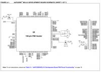
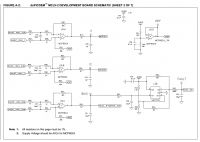
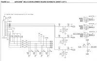
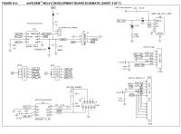
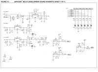
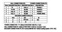
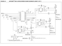
I am not sure but i am confusing everyone. Finally i have purchased the following board dsPICDEM™ MCLV-2. I am attaching the data sheet of the board and the motor. In this board we have option for both internal op amp or external op amp configuration. I have purchased the internal op amp. Now i have just started writing the software to drive the motor using Hall sensors. The motor is the following 10 pole Hurst motor (AC300020). The question i have asked is related to it. Please help me to make the motor working.
 

Attachments

  • MCLV-2-DS-52080a.pdf
    751.8 KB · Views: 113
  • Hurst Motor DataSheet.pdf
    463.4 KB · Views: 110

The board is supporting different motor control methods. Which are you trying to implement?
 

I am trying to control using Hall sensor. I am trying to create commutation table using Back emf.
 

This is the algorithm i plan to implement. I am trying to get the commutation table, but i don't know the method to get the table. I am trying to google and find out the method. Is the algorithm correct? Mainly I am trying to switch two legs one top and one bottom.
 

Attachments

  • Algorithm.pdf
    20.4 KB · Views: 129

How many wires you have in your motor? It should have 3 wires for the power and 5 wires for the Hall sensors (three for output and two for power: 5V and 0V).

You need the Hall sensors to accurately fix the speed (without the sensors the motor may be subject to slippage)- most motors have three sensors within a 120 arc.

It is not a rocket science- you need to report clearly and to the point.
 

Then I see you also have a built in encoder and the output is in quadrature. The motor is designed for some power servo application.

You need to connect them to the microprocessor. What is the resolution of the encoder? Normally it is 200 pulses /360deg- somewhat similar to common stepper motors.

How you have connected the motor? I suggest you do stepwise. First connect the three power lines - they go to the H bridge. See if you can get it running well and then see the Hall sensors next.
 

The motor has HALL A,B,C sensors, doesn't sound like quadrature sensor scheme.
 

The motor has HALL A,B,C sensors, doesn't sound like quadrature sensor scheme.

I see that the encoder has quadrature output; the hall sensors do not need quadrature. I presume that the Hall sensors will be used for speed and direction and the encoder will be used for positioning.
 

Commutation table using Hall sensors

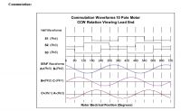
I did some effort to finally create a Commutation table to drive using Hall sensors. The waveform i found from the motor data sheet is as follows


I have taken the commutation table switches where the sine wave is maximum and minimum. Please help if it is correct or wrong which will help to start programming. I have attached the data sheet of the motor and the hardware board schematic.
 

Attachments

  • Hurst Motor DataSheet.pdf
    463.4 KB · Views: 115
  • MCLV-2-DS-52080a.pdf
    751.8 KB · Views: 106

Hi,
I presume that the Hall sensors will be used for speed and direction
the hall sensors are for block commutation... this is the simple method to make the BLDC motor run.

Klaus
 

Just to get some confidence and see the motor rotating, i want to start with hall sensors. Then i want to go for sine commutation. Only doubt i have is why at the peak of sine wave should i take the switch information.
 

Re: Commutation table using Hall sensors

Your data and graphs are correct; but you should use the transition to sync the sine waves. By the way, you are using a table to drive a PWM to synthesise the sinewave, right?

You need to take care while starting up (because you will need to ramp up the frequency slowly) and shutting down.

You can now run the motor to a accuracy of given rpm +/-1 because of sync problems. You can position the rotor using the encoder with a high degree of accuracy.
 

Re: Commutation table using Hall sensors

By the way, you are using a table to drive a PWM to synthesise the sinewave, right?
No. As i first step i will read the hall sensor values and just switch the legs.

You can position the rotor using the encoder with a high degree of accuracy.
As a first step i don't want to use encoder signals.

Yes it is inefficient but it will help me to see if i am programming properly and the motor is running. Any advise how to proceed.
 

Status
Not open for further replies.

Similar threads

Part and Inventory Search

Welcome to EDABoard.com

Sponsor

Back
Top