Continue to Site

Welcome to EDAboard.com

Welcome to our site! EDAboard.com is an international Electronics Discussion Forum focused on EDA software, circuits, schematics, books, theory, papers, asic, pld, 8051, DSP, Network, RF, Analog Design, PCB, Service Manuals... and a whole lot more! To participate you need to register. Registration is free. Click here to register now.

Simulation of a colpitt oscillator in ADS

Status
Not open for further replies.

virajsen

Newbie level 4
Joined
May 18, 2013
Messages
6
Helped
0
Reputation
0
Reaction score
0
Trophy points
1,281
Activity points
1,332
Dear All,

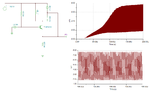
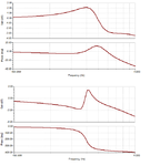
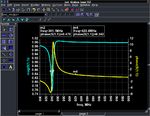
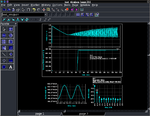
I tried to simulate the following oscillator design in ADS. O tried several methods but couldn't analyze the behavior of the Vout. Any help to simulate this circuit will be appreciated.

test.JPG
 

I was able to get it oscillating by reducing the VCC to 2V. But not oscillating frequency is wrong and the output voltage is in mV range.

I tried with step voltage as you suggested but didn't oscillate for that.

I attached results after the source voltage source.
simu.JPG
simu1.JPG
 

I did S simulation to check the resonant frequency of the system. It oscillates at correct frequency but huge attenuation can be observed at that frequency. Can anyone help me figure out why that is happening?

sim21.JPG
sim22.JPG
 

-Your oscillator circuit is completely wrong...
-DC Bias is very important in osc. circuits.
-Your oscillator simulations set-up is also wrong..
-That oscillator doesn't oscillate
-Oscillator circuits are not so simple circuits..
-I believe you don't know how a oscillator works..
-Read and work on oscillator much..
 

As mentioned, the circuit is questionable. With more suitable bias and bypass the circuit should oscillate as expected. It takes about 25 us of simulation time to start up.
 

Attachments

  • col_osc.png
    col_osc.png
    30.6 KB · Views: 294

    hust_st

    Points: 2
    Helpful Answer Positive Rating
In additional, BFG135 is not a proper transistor for oscillator applications regarding to my experiences.BFG193F is more suitable and lower noise BJT for <1GHz oscillators.
I have designed 5-6 oscillators in different bands, it worked well practically.
 

BigBoss, I only picked the specific transistor because that was the first spice model that came up in my library with enough frequency response.
 

I see that I misread the inductor value. Below are some phase/gain plots with the correct value of the working circuit (top) and your original ADS attempt (bot).

It is clear that the condition for oscillation is satisfied in the top plot and not for your circuit. Typical oscillator design starts by establishing good DC bias conditions and then by an open-loop analysis to determine enough gain and phase shift at the frequency of oscillation. This is then followed by doing a close loop harmonic balance simulation to determine non-linear results.
 

Attachments

  • col_osc1.png
    col_osc1.png
    21.3 KB · Views: 172

Ulrich is a very brilliant guy in all respects. We had a good phone conversation not so long ago one weekend while he was in NY relaxing on his yacht, and it included how he founded Compact Software that later sold to Ansoft, etc. He personally still uses the original Compact software, which was surprising to me.

Here is an attachment of advanced oscillator design using Ansoft Designer which could be applied to other packages equally.
 

Attachments

  • advanced_vco_design_using_ansoft_designer.pdf
    3.4 MB · Views: 216

Ulrich is a very brilliant guy in all respects. We had a good phone conversation not so long ago one weekend while he was in NY relaxing on his yacht, and it included how he founded Compact Software that later sold to Ansoft, etc. He personally still uses the original Compact software, which was surprising to me.
Here is an attachment of advanced oscillator design using Ansoft Designer which could be applied to other packages equally.

Absolutely, I sent a e-mail to him to ask why you use still Ansoft instead of another modern(!) software but he didn't respond me.
Isn't that ? If he demands a lifetime license from Keysight or AWR, they give this with a great pleasure, he is not ordinary man, he is Ulrich Rohde..
But he is still using Ansoft..There should be strong reason behind this in term of oscillator-like circuits which we don't know yet.I'm still wondering this phenomena..

We should definitely invite this guy to Edaboard if he accepts..
 

He used to belong to this forum, if you search posts under user 1NUL.

- - - Updated - - -

He told me he left because he felt offended by moderation of one of his threads. I tried to talk him into coming back, but his reply was he does not have time for petty issues. That is very unfortunate as there is a lot to learn from him.
 

I did S simulation to check the resonant frequency of the system.
It oscillates at correct frequency but huge attenuation can be observed at that frequency.
Your osc can not satisfy small signal oscillation condition at all.

Actually, we can not get steady state oscillation.
Warning detected by hpeesofsim in frequency search during HB analysis `HB1'.
Circuit is stable. No zero phase crossings of the injected current were
found. For oscillation, a negative going zero phase crossing should exist.
Will try fixed frequency amplitude search.

TRAN HB1_tran[1] <test_virajsen> time=(0 s->500 us)
Steady state reached and TAHB conversion started at t= 1.615e-07
Final transient frequency = 478.3369735 MHz
t=1.637e-07 100%

Code:
Options ResourceUsage=yes UseNutmegFormat=no EnableOptim=no TopDesignName="test_virajsen"
HB:HB1 MaxOrder=4 Freq[1]=480 MHz Order[1]=11 StatusLevel=2 Restart=no TAHB_Enable=1 OscPortName="HB1_OP" \
OutputPlan="HB1_Output" 

OutputPlan:HB1_Output \
      Type="Output" \
      UseNodeNestLevel=yes \
      NodeNestLevel=2 \
      UseEquationNestLevel=yes \
      EquationNestLevel=2 \
      UseSavedEquationNestLevel=yes \
      SavedEquationNestLevel=2 \
      UseDeviceCurrentNestLevel=no \
      DeviceCurrentNestLevel=0 \
      DeviceCurrentDeviceType="All" \
      DeviceCurrentSymSyntax=yes \
      UseCurrentNestLevel=yes \
      CurrentNestLevel=999

OscProbe:HB1_OP  Node[1]="vout" FundIndex=1 Harm=1 NumOctaves=2.0 Steps=20.0

Tran:HB1_tran HB_Sol=1 SteadyState=1 StatusLevel=3 StopTime=0.5 msec MaxTimeStep=0.1 nsec    \
MaxOrder=4 Freq[1]=480 MHz Order[1]=11 \
OutputPlan="HB1_Output"

Component:tahb_HB1 Module="ATAHB" Type="ModelExtractor" \ 
 Tran_Analysis="HB1_tran" HB_Analysis="HB1" \
 SaveToDataset=yes 

V_Source:SRC1  vcc 0 V_Tran=pulse(time, 0 V, 5 V, 0 nsec, 1 nsec) Vdc=5 V Vac=1 V SaveCurrent=1 
Short:OscTest1  _net176 ve Mode=0 SaveCurrent=no
model BJTM1 BJT NPN=1 PNP=0 Is=1e-16 Bf=100 Nf=0.993 Vaf=14 Ikf=0.15 Ise=4e-11 Ne=2.5 Br=6.7 Nr=1.2 Var=13 Ikr=0.008 Isc=1e-14 Nc=1.21 Rb=3.05 Irb=5e-5 Rbm=20 Re=0.8 Rc=8.75 Cje=7e-13 Vje=0.5 Mje=0.3 Cjc=1.1e-13 Vjc=0.85 Mjc=0.33 Xcjc=0.1 Cjs=0 Vjs=0.75 Mjs=0 Fc=0.4 Xtf=0.102 Tf=2e-12 Vtf=5 Itf=0.1 Ptf=23.5 Tr=1.0e-11 Kf=0 Af=1 Lateral=0 RbModel=0 Approxqb=1 Tnom=20 Eg=11 Xtb=0 Xti=3 
L:L1  vcc vc L=10 nH R=1e-12 Noise=yes  
C:C2  _net176 vc C=21.0998 pF 
C:C1  vcc _net176 C=21.0998 pF 
R:R4  vout 0 R=1 kOhm Noise=yes 
R:R3  ve vout R=1 kOhm Noise=yes 
R:R2  vb 0 R=1 kOhm Noise=yes 
R:R1  vcc vb R=1 kOhm Noise=yes 
"BJTM1":BJT1  vc vb ve Mode=1 Noise=yes
 

Attachments

  • Schematic.png
    Schematic.png
    138.7 KB · Views: 264
  • Small_Signal.png
    Small_Signal.png
    78.2 KB · Views: 250
  • Large_Signal.png
    Large_Signal.png
    72.5 KB · Views: 236

Status
Not open for further replies.

Part and Inventory Search

Welcome to EDABoard.com

Sponsor

Back
Top