Continue to Site

Welcome to EDAboard.com

Welcome to our site! EDAboard.com is an international Electronics Discussion Forum focused on EDA software, circuits, schematics, books, theory, papers, asic, pld, 8051, DSP, Network, RF, Analog Design, PCB, Service Manuals... and a whole lot more! To participate you need to register. Registration is free. Click here to register now.

Is my explanation of the frequency offset in this TRX circuti correct?

Status
Not open for further replies.

neazoi

Advanced Member level 6
Joined
Jan 5, 2008
Messages
4,119
Helped
13
Reputation
26
Reaction score
15
Trophy points
1,318
Location
Greece
Activity points
36,918
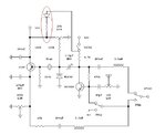
Hi, I am trying to transform a simple RX into a transceiver and I am playing around with the frequency offset mechanism. **broken link removed**
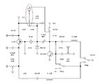
I have tested this mechanism and it works. I have explained of how I think it works in the last paragraph in this page.

Is my explanation correct?
The "the variable capacitor is connected "closer" to the ground through the (now switched on) BC549C transistor" is not a very good explanation.
Any corrections?
 

I'm not sure how this works in transmit mode as the antenna is shorted out by the switch.
Why do you need to shift the frequency between TX and RX, normally they should be on the same frequency?

Brian.
 
  • Like
Reactions: neazoi

    neazoi

    Points: 2
    Helpful Answer Positive Rating
I'm not sure how this works in transmit mode as the antenna is shorted out by the switch.
Why do you need to shift the frequency between TX and RX, normally they should be on the same frequency?

Brian.

Oh no, the circuit is not complete yet, it does not transmit. I am just trying to test the offset circuit. A small value capacitor will couple from the varicap anode to a buffer amplifier stage and then to a power amplifier. I am not sure that the transistor shunts (even imperfectly) the variable capacitor to the ground to change the frequency, or if is is caused by the preamp in another way. However it works, it offsets. It is also affected by the output load of the rf/af preamp, but this does not change (eg high impedance phones permanently connected) so this is not a problem.

This is an on/off transmitter (CW). You need the offset of the LO because otherwise you will not transmit at the same frequency that you receive.
For example suppose you want to receive 10.000MHz. On RX, You have to tune your LO to 9.999MHz or 10.001MHz for a 1KHz output tone. But on TX, you have to transmit at 10.000MHz, not 9.999MHz or 10.001MHz. So the LO has to offset.
 

The easiest method then is a diode switch. Add a small capacitor (variable?) and diode in series across the tuning capacitance and switch a voltage across it to forward or reverse bias it. When conducting it will appear as a low resistance, when blocked it will appear almost open circuit. You can also do it by switching a resistor across one or the other sides of the potentiometer to the wiper so you get a slight increase or decrease in varicap voltage.

Brian.
 
  • Like
Reactions: neazoi

    neazoi

    Points: 2
    Helpful Answer Positive Rating
The easiest method then is a diode switch. Add a small capacitor (variable?) and diode in series across the tuning capacitance and switch a voltage across it to forward or reverse bias it. When conducting it will appear as a low resistance, when blocked it will appear almost open circuit. You can also do it by switching a resistor across one or the other sides of the potentiometer to the wiper so you get a slight increase or decrease in varicap voltage.

Brian.

I like the resistor way you proposed. No tricky variable capacitor with stray capacitance. Why haven't I thought it before? :-?
A potentiometer instead of the resistor, would give a variable settable offset.
The only problem I see with this, is that when using crystals the pulling is only 2KHz or so. This means that the frequency pot has to be switched to 1khz only because the other 1khz should be used for the offset. So this limits the tuning range.

Can you think a of a way in which this resistor could be electronically switched in and out during TX/RX? I am doing the TX/RX switching of the transceiver using VCC, enabling or disabling different parts of the circuit, although I am not convinced this is good yet, since I get some frequency detuning at the beginning of each switching.
 

If you are switching by enabling VCC to other parts of the circuit, try simply adding a resistor between the switched VCC and the tuning voltage, maybe adding a series diode if there is risk of current flowing back. If that gives the wrong shift direction, use the switched VCC to bias a transistor and connect it's collector through a resistor to the tuning voltage so it pulls it slightly down. I appreciate that with such narrow tuning range your shift is limited but that would always be a limitation when pulling a crystal.

Brian.

Like this?
I think I have an error
 

Attachments

  • y.JPG
    y.JPG
    50.5 KB · Views: 82

Almost - the new resistor goes to the wiper of the tuning potentiometer or to the top of the varicap diode.

Brian.
 
  • Like
Reactions: neazoi

    neazoi

    Points: 2
    Helpful Answer Positive Rating
Almost - the new resistor goes to the wiper of the tuning potentiometer or to the top of the varicap diode.

Brian.

Like this?

If the wiper of the potentiometer is close to the VCC then the new resistor and diode will have no effect on the frequency pulling, is that right?
 

Attachments

  • y.JPG
    y.JPG
    50.3 KB · Views: 88

Unfortunately yes, but moving the resistor to the varicap will help a little. You have to bear in mind that the amount you can pull a crystal is very small anyway, even with a large voltage. Even switching in a physical capacitor won't help, the further you pull the crystal the less likely it is to work properly.

Brian.
 

Status
Not open for further replies.

Part and Inventory Search

Welcome to EDABoard.com

Sponsor

Back
Top