Continue to Site

Welcome to EDAboard.com

Welcome to our site! EDAboard.com is an international Electronics Discussion Forum focused on EDA software, circuits, schematics, books, theory, papers, asic, pld, 8051, DSP, Network, RF, Analog Design, PCB, Service Manuals... and a whole lot more! To participate you need to register. Registration is free. Click here to register now.

Interfacing 4-20mA to MCU

Status
Not open for further replies.

electrohawk

Newbie level 4
Joined
Sep 12, 2017
Messages
6
Helped
0
Reputation
0
Reaction score
0
Trophy points
1
Activity points
70
Hello, I would like to design a 4-20mA sensor interface for my MCU. I know all i need is a 250 ohm resistor, an opamp and an A2D. However, I need to add protection such as reverse protection for the sensor and protections on the point where I am reading from the sensor. What do you think is the best way to to this? TVS on the 250 ohm and a normal diode on the DC input of the sensor? Please help as I am confused and can't find a suitable solution. Thank you!
 

Hi,

This has been discussed many times here. A forum search will bring a lot of results.

* I´d use a smaller value resistor to get some headroom. If the voltage drop is no problem, then I recommend max. 200 Ohms.
* No OPAMP is needed
* Use an appropriate RC filter. I recommend that tau is about 5 times the sampling rate. Select series R in the range of 1k...10k. Read ADC datasheet about input impedance.
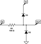
* for protection use two schottky diodes at the ADC input. One to GND, the other to VCC. (or a double diode, like BAT54S)
* Reverse protection: A diode (schotty or not) in series with the 4..20mA signal line.

Klaus
 
  • Like
Reactions: VSef

    VSef

    Points: 2
    Helpful Answer Positive Rating
Thank you for you reply.

I though adding an op amp in differential mode will improve common mode rejection.

* for protection use two schottky diodes at the ADC input. One to GND, the other to VCC. (or a double diode, like BAT54S)

Why a schottky and not a TVS? and do you mean something like this ?

oKptw.png

Thank you
 

Hi,

OPAMP:

If one resistor leg is connected with GND anyway there is no common voltage to take care of.

TVS is an absolute voltage limiting. Now assume the ADC is not powerd up, the TVS limits to 5V...then this is out of ADC specification most probably.
Additinally with TVS you have a wide range of current...beginning from when it starts to conduct... maybe below 5V, then his current is missing in your measurement current --> measurement error.
And with high input current, then the voltage is relatively high.

A schottky diode usually keeps voltages within ADC specifications, while causing no considerable error current. It limits voltages relative to VCC and GND respectively.

R1 --> value like in my post#2

Klaus
 
  • Like
Reactions: VSef

    VSef

    Points: 2
    Helpful Answer Positive Rating
Status
Not open for further replies.

Part and Inventory Search

Welcome to EDABoard.com

Sponsor

Back
Top