Continue to Site

Welcome to EDAboard.com

Welcome to our site! EDAboard.com is an international Electronics Discussion Forum focused on EDA software, circuits, schematics, books, theory, papers, asic, pld, 8051, DSP, Network, RF, Analog Design, PCB, Service Manuals... and a whole lot more! To participate you need to register. Registration is free. Click here to register now.

Using PIC16F18856...What type of input should our DALI RX pin be?

Status
Not open for further replies.
T

treez

Guest
Hello,

We are using PIC16F18856 with a 3V Vdd rail.
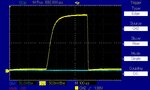
We are using Port RB3 as an input to receive DALI signals, as the attached shows (a close up of part of the pulse stream). The rise time of the received pulse is long, and we wish to know what is the minimum value for logic high? (VIH)..
Page 610 of the PIC16F18856 datasheet states that a logic high voltage varies depending on whether the input pin is either a TTL buffer or a Schmitt trigger buffer.
The INVLB register seems to deal with whether or not the pin is Schmitt trigger or TTL. We obviously want it to be TTL as the VIH value is lower. (ST = 2.4V for VIH; TTL = 1.55V for VIH)
However, do you think we should really choose to declare the DALI RX pin as a I2C pin? (VIH = 2.1V).


It amazes us that there are so many different types of input available for the RB3 port, each one of them having a different VIH. We want lowest VIH but feel that “I2C” is more suitable for a DALI RX pin?
PIC16F18856 Datasheet:
https://ww1.microchip.com/downloads/en/DeviceDoc/40001824B.pdf
 

Attachments

  • DALI signal input to port RB3.jpg
    DALI signal input to port RB3.jpg
    110.5 KB · Views: 132

Your picture shows a 3V signal so why are you worried about the threshold? I would select the input type as ST if there was noise present as it gives better immunity against low level fluctuations but surely you are not connecting the DALI signal directly to the pin anyway.

Brian.
 
  • Like
Reactions: treez

    T

    Points: 2
    Helpful Answer Positive Rating
Thanks, no you're right, this is the DALI signal after its been passed through the RX optocoupler.
The long-ish rise time of the signal worries us, because the DALI code libraries may try and read the signal before its had chance to go high?
We can make it rise faster by reducing the pullup resistor value, but this means more dissipation in our linear regulator which feeds off the HV DC Bus.
 

Hi,

If there is a "capture" function in your microcontroller, I'd use it as input for the DALI signals.
It may simplify the software. But you may use bit banging anyway.

Klaus
 

I think you are looking for ghosts in the machine when there are none. Try showing the waveform with a whole byte rather than one bit so you can see what the UART really has going into it.

Depending on what type of opto-coupler you are using, you might be able to significantly sharpen the edges by configuring it differently or adding a bias leak resistor. If your type allows it, you can get faster edges AND less current consumption at the same time at the expense of slightly higher input (LED side) current. In any case, I wouldn't expect more than about 0.5mA output current should be needed with the output side 'on' and virtually zero when 'off' so the average over time would be very low.

There is no chance of an input pin being read prematurely and seeing the wrong logic level. If you are using a UART/USART, the sampling time is fixed by the Baud rate generator and the input circuit uses a majority 'voting' system. On most UARTs the sampling rate is 16x the bit rate but I think Microchip use 5x with a majority of 3 needed to qualify the bit state. This buys you a large increase in confidence that the data is correctly recognized.

Brian.
 
  • Like
Reactions: treez

    T

    Points: 2
    Helpful Answer Positive Rating
But you may use bit banging anyway.
Thanks, yes, DALI commands are always the same…one start bit, eight address bits, eight data bits, and two stop bits. The dimming level is in the eight data bits.
As such, I cannot understand why people don’t just bit bang it….bit banging DALI is far easier than trying to hoik all those enormous DALI code libraries around. Ive seen a software dept of a huge lighting company at nervous breakdown level due to the complexity of the software involved with the DALI libraries. ..literally saw the head of software and head of electronics having a stand up row in the middle of the engineering office…all over DALI. Why don’t people just bit bang the DALI?...what is the problem that happens when it is bit banged?
The DALI controller does not need an “acknowledge” for the bytes that it sends….so you don’t even have to bit bang a response.
The great mystery of the lighting industry is why people don’t just bit bang the DALI. Do you know the answer?
DALI was invented by a lighting company called Tridonic…now do you think that any company (not referring to Tridonic here) would give a protocol away to all its competitors…and not shove a few Trojans into the bundle?
From my experience, highly experienced software engineers trying to handle the DALI libraries end up in one heck of a mess.
 

I'm not sure what I2C has to do with the issue you raise in your original question. It is not one of the types listed for RB3 in Table 1-2 of the data sheet you link to.
Also, given the wave form you have shown, you are talking about perhaps 100uSec between a low threshold and a much higher one. Does that *really* make a difference in your design given that the pulse is at least 3 times longer than that?
Bit-banging, especially on receive, is very sensitive to timing in that you (generally need to sample multiple times within the 'bit width' to make sure that you have correctly sampled the '0' or '1'. If a pulse is 400uSec (as in your diagram) that means you should be sampling (at least) every 50uSec and working out the correct state at the middle of the bit time. (Can you afford the processor time for that given a maximum 8MHz instruction clock?)
Given the bit-level protocol that you have mentioned, I would imagine that the 'enormous' code libraries that you mention are more to do with interpreting the message than the bit-level encoding/decoding.
Susan
 
  • Like
Reactions: treez

    T

    Points: 2
    Helpful Answer Positive Rating
I agree entirely with Susan. The 'bit banging' is only the final step in driving the transmit pin and given that it uses standard 8N1 serial data it is much easier to use the on-board UART. All the library stuff is to interpret incoming data and format outgoing data. You can almost certainly dispense with most of the DALI library and write code only covering the commands you use.

The real problem with DALI is the weird slave addressing it uses and how the controller finds out which addresses are on the network. There is an excellent explanation of the "0ne-wire" address discovery method on Maxim's web site, as far as I can tell it will work with DALI as well. All one-wire devices have a factory set unique serial number but I can't see it is any different to a randomly generated one as far as discovering it is concerned.

Brian.
 

Hi,

I may be mistaken...
But DALI isn´t truely 8N1,
It more is a mix between 8N2 and 16N2
and additionally it is manchester encoded.

I have no idea how to use a standard UART for this protocol.
(But I spent no much time to think about it, either)

Klaus
 

Oops! You are right Klaus, my mistake. OK, forget the UART, at least for transmitting but bit banging is still easy anyway.

Brian.
 

Status
Not open for further replies.

Part and Inventory Search

Welcome to EDABoard.com

Sponsor

Back
Top