Continue to Site

Welcome to EDAboard.com

Welcome to our site! EDAboard.com is an international Electronics Discussion Forum focused on EDA software, circuits, schematics, books, theory, papers, asic, pld, 8051, DSP, Network, RF, Analog Design, PCB, Service Manuals... and a whole lot more! To participate you need to register. Registration is free. Click here to register now.

Calculating base resistor for controlling common cathode of 7 segment display

Status
Not open for further replies.

garvind25

Full Member level 3
Joined
Oct 28, 2012
Messages
176
Helped
0
Reputation
0
Reaction score
1
Trophy points
1,298
Activity points
3,066
Hi,

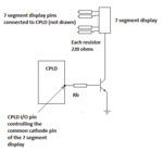
I wanted to interface a common cathode 7 segment display unit with a CPLD (XC2C128). To control if the 7 segment unit is enabled, I am planning to interface the common cathode pin through an npn transistor (as shown in the attachment). When the corresponding CPLD pin will be high, the transistor will be switched on with 3.3 v base voltage and vice versa. How do I select the value of Rb pls. I am fixing the current through each segment of the display to be 6 mA. So in the minimum case when only on segment is switched on, collector current will be 6 mA and Rb is coming out to be 43.33Kohm (assuming Hfe=100). In the maximum case, when the current will be 6X8=48 mA, the Rb is coming out to be 5.42 Kohms. So which value of resistor should I choose for transistor base resistance. I will be using 3.3v I/O standards (ie. logic 1 is 3.3v).

Thanks,
Arvind Gupta
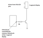
Transistor_base_resistance.png
 

You don't calculate the resistor for hfe=100 but a lower "forced beta" value to
achieve low transistor saturation voltage.
 

In other words, what FvM said is that you need to ensure saturation at the minimum value of hfe and the maximum collector current.
Select your base resistor as such:
Rbase<hfemin·(3.3-Vbe)/Icmax
 

Thanks for your replies. I was trying to derive the formula as below:

Icmax. > Bmin X Ib --- for tx. to remain in saturation
KVL in the base emitter loop gives:
Ib = (3.3 –Vbe)/Rb
From these two expressions, one gets:
Rb > Bmin (3.3 - Vbe)/ Icmax.

My queries are:
1. How am I getting a different equation than yours pls?
2. In the first expression, why are we considering Bmin than Bmax.
3. For calculation purpose, which value of Vbe should I use: Vbesat. Or Vbeon (min, typical, max) ?
4. Also should the calculations not be done for Icmin to ensure that the tx. remains in saturation for least current?

Thanks again,
Arvind Gupta
 

Hi,

I assume you are trying to generate a current limiter with the use of base_current and gain of the transistor.
This won't work satisfying, because B has a very large range. It is not exactely "100" ... more likely it has a range of 50..200.
--> Use a current limiting resistor at each anode, and use the cathode transitor as saturating switch.

There are many 7 segment displays where you can see how to do this.
Use one of these circuits as your reference circuit.

It's good habit not to drive the disply current from the PLD directely. Use a driver circuit.

I wonder why you calculate with "6" times the segment current.
Displaying an "8" needs all seven segments.

Klaus
 

1. How am I getting a different equation than yours pls?
Because of wrong saturation equation relating the base current and collector current.
2. In the first expression, why are we considering Bmin than Bmax.
Because you do not know if the transistor you are going to buy has the max beta, min beta or any value in between. You want to ensure saturation for whatever transistor you buy, which leads to calculate for the worst case.
3. For calculation purpose, which value of Vbe should I use: Vbesat. Or Vbeon (min, typical, max) ?
Vbe(sat) max.
4. Also should the calculations not be done for Icmin to ensure that the tx. remains in saturation for least current?
No. Is more difficult to achieve saturation with little collector current or with a lot of collector current?
 

I would choose Rb of 1k with general purpose transistors, corresponding to a forced beta of 18. In case of doubt look at the Vce,sat versus Ib curve for the selected transistor.

Some modern transistors have a guaranteed low Vce,sat with high current gain, they can use higher Rb values.
 

Thanks for your reply Klauss. I am assuming current in each segment of 7 segment display to be 6 mA (for this purpose I will be connecting eight 220 ohm resistance in series with 8 anodes of the display; pls. see modified diagram attached). And if I have to display "8." then all segments will be on. Hence the max. current 6mA X 8 = 48 mA.

Since B has a large range, which value should I use to calculate, the min. possible I guess? In BC547 the min. DC gain is 110. Datasheet **broken link removed**. So now, how do I proceed to find the value of Rb?

Arvind Gupta.

Transistor_base_resistance.png

- - - Updated - - -

Because of wrong saturation equation relating the base current and collector current.

No. Is more difficult to achieve saturation with little collector current or with a lot of collector current?

Thanks for your reply CataM.

Pls. inform me of the right equation relating base current and saturation current in an npn bjt for saturation in this case pls. And thanks again.

Yes, though you are right that it is difficult to bias a tx. with minimum collector current, it has to be done in this case (suppose I need to display only the dot point in the 7 segment display. In such a case the current through the 7 segment display will be least -- corrsponding to the LED of 1 segment ie. in this case 6 mA )

Regards,
Arvind Gupta
 

Hi,

Datasheet is always a good idea!.

See how they defined saturation state:
IC = 10mA , Ib = 0.5mA --> B = 20
IC = 100mA, IB = 5mA --> again B = 20.

So in your case: 48mA (Yes. I was wrong with may "6 times" assumtion) --> / 20 = 2.4mA.

***
The complete path for the base is:
3.3V --> microcontroller --> base resistor --> transistor --> GND
microcontroler voltage drop high for driving 2.4mA: maybe 0.3V --> look into the datsheet
base resistor --> to be calculated
Transistor V_BE_max --> 900mV

Voltage across resistor: 3.3V - 0.3V -0.9V = 2.1V
Current: 2.4mA

Now just use Ohm´s law. (I don´t want the complete job of you)

Klaus
 

See how they defined saturation state:
IC = 10mA , Ib = 0.5mA --> B = 20
IC = 100mA, IB = 5mA --> again B = 20.

So in your case: 48mA (Yes. I was wrong with may "6 times" assumtion) --> / 20 = 2.4mA.

Sorry... could not find this on the given link of the datasheet. They have simply defined in page 1 that hfe(min)=110 and hfe(max)=800 {for Vce=5v and Ic =2mA}. Also, in page 2, figure 3 of the datasheet, they have shown hfe to be constant at 110 for Ic upto 50 mA (approx). Hence pls. tell me the where did you come up with this data?

microcontroler voltage drop high for driving 2.4mA: maybe 0.3V --> look into the datsheet
base resistor --> to be calculated

Klaus

Why should there be an additional voltage drop of 0.3v. As I understand, the KVL equation will be:

3.3 - (voltage drop across Rb) - (voltage drop across base emiiter junction) = 0

ie.

3.3 -Ib X Rb - Vbe(sat) = 0

So if I know Ib, I can determine Rb.

Thanks again,
Arvind Gupta
 

Pls. inform me of the right equation relating base current and saturation current in an npn bjt for saturation in this case pls. And thanks again.
Post #3, which is the conclusion of post #9. If the datasheet is using forced beta of 20 in their datasheet, then use that as minimum beta, or lower.
 

Sorry... could not find this on the given link of the datasheet.
You didn't read thoroughly. There's figure 4 for Ic/Ib = 10 and a Vce(sat) specification in the electrical characteristics table for Ic/Ib = 20. Strictly speaking, Ic/Ib in saturation isn't current gain B. It's an externally enforced current ratio, sometimes called "forced beta". Obviously forced Ic/Ib can be arbitrarily smaller than B but not larger.

The operation is called saturated switching, you can choose useful Ic/Ib values based on assumptions even if saturation behavior isn't fully specified in the datasheet, e.g. based on experience.
 
  • Like
Reactions: CataM

    CataM

    Points: 2
    Helpful Answer Positive Rating
Hi,

Please accept that your calculation with an hfe of about 100 is for linear operation, which is not valid here.
But you should use saturated switch ooeration. Datasheet shows a ratio of 20.

Why should there be an additional voltage drop of 0.3v.
I already told you to read the datasheet on this. Look for VOH.

Klaus
 

hFE (beta) is never used for a saturated transistor switch. It is used when a transistor is an amplifier that always has plenty of collector to emitter voltage so that it is never saturated.
The datasheet for most little low current transistors show that it saturated fairly well when its base current is 1/10th to 1/20th of its collector current even if its hFE is 300.
 
  • Like
Reactions: CataM

    CataM

    Points: 2
    Helpful Answer Positive Rating
Hi KlausST, CataM, FvM and Audioguru,

Thanks for your replies. Yes, I checked the datasheet of the CPLD. Voh is Vccio – 0.2. There were 2 test conditions mentioned: First condition: IOH = –8 mA, VCCIO = 3V then Voh= VCCIO – 0.4V. Second condition IOH = –0.1 mA, VCCIO = 3V then VOh= VCCIO – 0.2V. Since base current will be small, I am assuming the second condition ie Voh=Vccio-0.2v. BTW I am setting Vccio to be 3.3v where as the test conditions as per datasheet is 3.0v. Will that make a difference?

OK. I accept the forced beta concept (this was the first time I came across this concept). But still there is one more doubt. As per post #3, the calculations have been done for the max. value of collector current ( ie when all the 8 segments will be on; 48mA). But when only 1 segment is on, then the current in the common cathode terminal and consequently collector current will be reduced to 6 mA. Do you suppose the resistor Rb value which was calculated for Ic corresponding to current from 8 segments will still keep the transistor in saturation for such low current? Or, should I not do the other way round ie. calculate the value of Rb for 6mA and use it for collector currents up to 48mA? Or what else is the solution pls?

Regards,
Arvind Gupta
 

Do you suppose the resistor Rb value which was calculated for Ic corresponding to current from 8 segments will still keep the transistor in saturation for such low current?
Surely, the transistor is even more saturated at lower Ic.
 

If you calculate a base resistor for a saturation voltage loss of only 0.2V when the collector current is only 6mA then when all segments turn on causing a collector current of 48mA, the saturation voltage loss might be so high that there is not enough remaining voltage for the LEDs to produce any light or they will be very dim.
 

Status
Not open for further replies.

Part and Inventory Search

Welcome to EDABoard.com

Sponsor

Back
Top