Continue to Site

Welcome to EDAboard.com

Welcome to our site! EDAboard.com is an international Electronics Discussion Forum focused on EDA software, circuits, schematics, books, theory, papers, asic, pld, 8051, DSP, Network, RF, Analog Design, PCB, Service Manuals... and a whole lot more! To participate you need to register. Registration is free. Click here to register now.

transistor region in Cadence

Status
Not open for further replies.

bio_man

Full Member level 2
Joined
Mar 30, 2010
Messages
144
Helped
2
Reputation
4
Reaction score
4
Trophy points
1,298
Activity points
2,698
Hi,

I know that I can check the transistor operating region in cadence by checking each mosfet using:
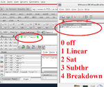
1) OP option in calculator, as shown in the attached screenshot.
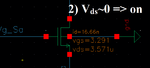
2) checking the Vds, if it is close to zero it means transistor is conducting (but can't say it is linear, sat ..etc)
However, this is tedious job, I have many transistors in the circuit I want to check them by one look. So, can anyone suggest how to show "Annotate" the transistor operating region on the schematic straightforward?


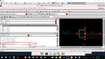
my second question about the ''Estimated operating region'' parameter in transistor: it is always showing Sat, what is the significance of this parameter? screenshot attached!

thanks in advance folks!

- - - Updated - - -

Also, kind of related question. how can I see what is the status of the transistor (sat, linear, off, ..etc) in specific interval of time? suppose I have clocks that switching some transistors on and off, I want to see how transistor changes its region of operation without make two difference simulations
 

Attachments

  • Transistor_region_cadence_1.png
    Transistor_region_cadence_1.png
    204.7 KB · Views: 1,853
  • Transistor_region_cadence_2.png
    Transistor_region_cadence_2.png
    17.6 KB · Views: 533
  • Transistor_region_cadence_Paramter.png
    Transistor_region_cadence_Paramter.png
    466.5 KB · Views: 654

I don't trust the "region" stuff. And I have never made
one bit of use, of it, in a couple decades of Cadence
based design.

And it's likely that only a few devices in the design
really care about "region" anyway. If you know the
ones that matter, maybe checking is not so tedious.
 
I don't trust the "region" stuff. And I have never made
one bit of use, of it, in a couple decades of Cadence
based design.

And it's likely that only a few devices in the design
really care about "region" anyway. If you know the
ones that matter, maybe checking is not so tedious.

just curious, is there a reason why you trust it? it makes sense when comparing Vds and Vgs values.
 

Back-annotation of the transistor operating region into schematics may actually be helpful for an overview. How it's done depends on your software version. Check this thread.

"Sat" region (#2) means Vds < Vd_sat .
 

"Sat" region (#2) means Vds < Vd_sat .

Yah, but my point is this "Sat" parameter always there in all transistors and it's customized parameter so you can change it yourself. I'm wondering for what it can be used?
 

... is this "Sat" parameter always there in all transistors and it's customized parameter so you can change it yourself.
Yes, it's always there in all transistors, and, no, it cannot be customized: VDS,sat depends on Id and the inversion mode, see this diagram:
Binkley__p92_saturation_voltage Kopie.png

I'm wondering for what it can be used?
To differentiate between the saturation and the linear region.
 
no, it cannot be customized: VDS,sat depends on Id and the inversion mode

thanks erikl for your feedback, and I know these operating regions are highly dependent on the biasing conditions. I'm totally aware of all inversion modes in the transistor. However, my point is this specific parameter found in the transistor parameters list which has nothing to do with the status of the transistor, it still showing 'sat' while the transistor is OFF 'region 0' in the schematic, check attached screenshot. Also, when you click on the parameter, a drop-down list appears where you can select the estimated mode of operation (off, triode, sat, subthr).

So, my question: what is the significance of determining the estimated mode of operation for the transistor? does this reflect any valuable information in the output file or something else?
 

Attachments

  • Transistor_region_cadence_Paramter2.png
    Transistor_region_cadence_Paramter2.png
    49.5 KB · Views: 144

... it still showing 'sat' while the transistor is OFF 'region 0' in the schematic, check attached screenshot.
Where does it show 'sat'? In the schematic, correctly the region=0 is backannotated, which means OFF, as you wrote.

... when you click on the parameter, a drop-down list appears where you can select the estimated mode of operation (off, triode, sat, subthr).

what is the significance of determining the estimated mode of operation for the transistor? does this reflect any valuable information in the output file or something else?

I don't know, sorry. This drop-down list wasn't yet available when I used the C@dence tools (icfb v. 5.1.41 if I remember well, a few decades ago ;-) ). Try & find something about it in the C@dence docu.
 

Status
Not open for further replies.

Part and Inventory Search

Welcome to EDABoard.com

Sponsor

Back
Top