palmeiras
Full Member level 6
- Joined
- Feb 22, 2010
- Messages
- 375
- Helped
- 61
- Reputation
- 122
- Reaction score
- 50
- Trophy points
- 1,308
- Location
- South America
- Activity points
- 4,199
Hi guys,
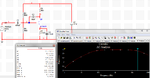
Please, consider the attached circuit.
Based on the Miller theorem, C3 (miller capacitor) can be divided in two capacitors connected to ground. The first one (CX) is connected from node 2 and ground, and the second (CY) one is connected from node 3 (vout) and ground.
The capacitor CY is given by C3/(1-(1/AV)). Since this circuit has large gain, CY ~ C3.
Therefore, if we consider that R2 << ro, we can calculate the pole frequency at node 3:
f = 1/(2*pi*R2*CY) ~ 8kHz.
R2 = 2k
CY = 10n
However, the bode plot of my simulation show that the high frequency corner (-3 db) frequency is about 20 kHz. (NOT 8 kHz). Why?
Why is there such discrepancy?
Thanks