Noct1
Newbie level 3
Hello,
As a chemist, a part of my job is to use RF circuits to follow chemical reactions. It is a very powerful tool but, since I have no solid training in RF, I sometimes have difficulty with some concepts.
I understand that if I measure the reflection (S11) and transmission (S21) coefficients of a microstrip with a V.N.A, the values will follow this equation :
|S11|² + |S21|² + losses = 1
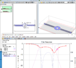
The circuit that I use is a microstrip coupled with a spiral resonator. It has 6 resonances between 10 and 20 GHz. When I calculate |S11|² + |S21|², it is is nearly equal to 1 before the first resonance, then it decreases to 0.6 with "peaks" within the frequency range. I noticed that the maxima of theses peaks in S11²+S21² are located when S11 is equal to S21.
I know that this means I have strong losses in my circuit but can you tell me what are the very likely causes of theses losses? Can they be due to a poor calibration? Or maybe a bad adaptation of the circuit?
I joined S11/S21 plots (S21 is the dotted line) and the S11²+S21² plot so you can see :

Thank you very much!
As a chemist, a part of my job is to use RF circuits to follow chemical reactions. It is a very powerful tool but, since I have no solid training in RF, I sometimes have difficulty with some concepts.
I understand that if I measure the reflection (S11) and transmission (S21) coefficients of a microstrip with a V.N.A, the values will follow this equation :
|S11|² + |S21|² + losses = 1
The circuit that I use is a microstrip coupled with a spiral resonator. It has 6 resonances between 10 and 20 GHz. When I calculate |S11|² + |S21|², it is is nearly equal to 1 before the first resonance, then it decreases to 0.6 with "peaks" within the frequency range. I noticed that the maxima of theses peaks in S11²+S21² are located when S11 is equal to S21.
I know that this means I have strong losses in my circuit but can you tell me what are the very likely causes of theses losses? Can they be due to a poor calibration? Or maybe a bad adaptation of the circuit?
I joined S11/S21 plots (S21 is the dotted line) and the S11²+S21² plot so you can see :
Thank you very much!