searchforknowledge
Junior Member level 2
Hi everyone,
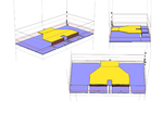
I am simulating a simple combiner in Sonnet but I am getting strange results (specially at DC). Let me describe the combiner shown in the Figure 1. The combiner has a width (metal 5) of 18.5 um that will be connected to bases of transistor through vias because the contacts for the bases of transistor are on metal 1. I need to use metal 1 also as a ground plane for the design of my power amplifier that is why I shorted it to the sonnet box. The ground plane is separated from port 2 and port 3 of combiner by small gap allowed by the technology I am using. I have defined all ports as standard with some reference plane.
Can someone please help me and point out what is going wrong.