girishklm
Newbie level 4
Dear sir,
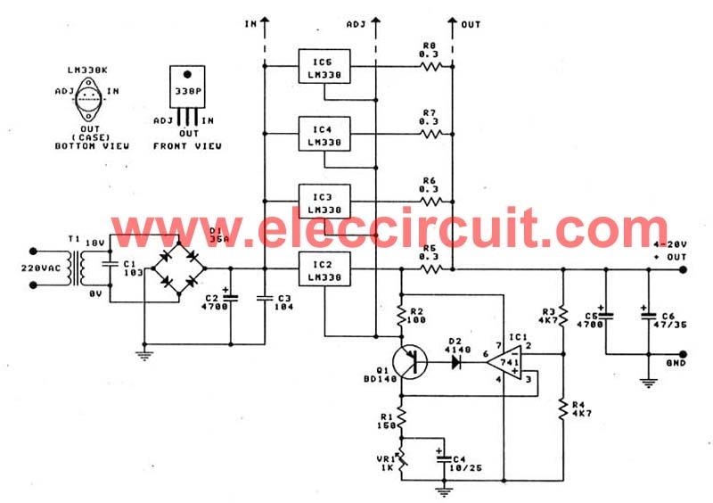
i was writing this to get information for rectify the problems i am facing in my ATX power supply. i Let me tell you from beginning. i have observed my atx power supply can supply 20A in 12 v so that i planned to make a work bench power supply. i found a 0-24v 20 A voltage regulator circuit using LM 338T from internet and i made it.That circuit has 4 LM338T which was parallel to each other so that it can supply 20 A( LM 338T can supply 5A as per the data sheet ) i have taken -12v and +12V line so that i thought i can make a variable power supply line of 0- 24V 20 A :???: when i switched it on my volt meter reading was accurate . it was showing 0-24v variable voltage and within few second my power both transister MJE13007 was blown like bomb :bang: . suddenly i switched it off and checked both power transistor was blown and observed dide 4148 and a resistor attached to that area also blown i. i assumed the voltage regulator circuit i made acted as a load to SMPS and tried to drawn 20A current from -12 to +12 and failed becase at -12 v it can only supply 500 mA .I changed everything i have used MJE13009 instead of 13007 so that it can handle more power . i removed the fuse of circuit and connected a 100W bulb so that if anything failed from primary circuit will make the bulb glow and protect the circuit from damage and we can understand it . when i switched it on the bulb filament was glowed like cinder and off suddenly . i observed nothing was shorted . if it yes the bulb will glow bright light mode . i have checked the out put at 12v and found it was .11v and but the +5v line was present . i checked the green wire supply which is using to short with ground to switch on smps and i got 2.15v in the line . i thout to check the main filter capacitor voltage at primary . In india the supply input line voltage is 230-240v so the smps filter capacitor should have 240*1.4142= DC 339V but it has only 150V Dc so i thought the power transistor line was not switched on and i suspected PWM which was giving signal to switch the primary section from secondary via a opto coupler 817 D. i changed the PWm ic TL494 too and everything was same as before. my mosfet is 2N60 which is fine with my multi meter . can you guide me to solve this ?? :bang::bang::bang:
i was writing this to get information for rectify the problems i am facing in my ATX power supply. i Let me tell you from beginning. i have observed my atx power supply can supply 20A in 12 v so that i planned to make a work bench power supply. i found a 0-24v 20 A voltage regulator circuit using LM 338T from internet and i made it.That circuit has 4 LM338T which was parallel to each other so that it can supply 20 A( LM 338T can supply 5A as per the data sheet ) i have taken -12v and +12V line so that i thought i can make a variable power supply line of 0- 24V 20 A :???: when i switched it on my volt meter reading was accurate . it was showing 0-24v variable voltage and within few second my power both transister MJE13007 was blown like bomb :bang: . suddenly i switched it off and checked both power transistor was blown and observed dide 4148 and a resistor attached to that area also blown i. i assumed the voltage regulator circuit i made acted as a load to SMPS and tried to drawn 20A current from -12 to +12 and failed becase at -12 v it can only supply 500 mA .I changed everything i have used MJE13009 instead of 13007 so that it can handle more power . i removed the fuse of circuit and connected a 100W bulb so that if anything failed from primary circuit will make the bulb glow and protect the circuit from damage and we can understand it . when i switched it on the bulb filament was glowed like cinder and off suddenly . i observed nothing was shorted . if it yes the bulb will glow bright light mode . i have checked the out put at 12v and found it was .11v and but the +5v line was present . i checked the green wire supply which is using to short with ground to switch on smps and i got 2.15v in the line . i thout to check the main filter capacitor voltage at primary . In india the supply input line voltage is 230-240v so the smps filter capacitor should have 240*1.4142= DC 339V but it has only 150V Dc so i thought the power transistor line was not switched on and i suspected PWM which was giving signal to switch the primary section from secondary via a opto coupler 817 D. i changed the PWm ic TL494 too and everything was same as before. my mosfet is 2N60 which is fine with my multi meter . can you guide me to solve this ?? :bang::bang::bang: