Continue to Site

Welcome to EDAboard.com

Welcome to our site! EDAboard.com is an international Electronics Discussion Forum focused on EDA software, circuits, schematics, books, theory, papers, asic, pld, 8051, DSP, Network, RF, Analog Design, PCB, Service Manuals... and a whole lot more! To participate you need to register. Registration is free. Click here to register now.

PSPICE SMPS input current limit.

Status
Not open for further replies.

sk614

Newbie level 5
Joined
Aug 9, 2017
Messages
10
Helped
0
Reputation
0
Reaction score
0
Trophy points
1
Activity points
65
wave1.jpg
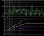
I am simulating a flyback converter. So far I think things are working comparing the output voltages and hand calculations. However...I dont think the simulation is realistic. From the waveform, the top plot is the input current. Do I need to limit that current to make the simulation more realistic?

- - - Updated - - -

I think I want something like this in Pspice to limit the current.
capture-png.95781
But don't know how to implement in Pspice.
 

What aspect of the source supply do you think you
want to emulate?

Is the "case" one where you switch-connect to an
established supply? One where you are connected
but disabled (EN, UVLO) until your converter decides
(or is told) to start? One where your converter is
ready to go and the source supply ramps up?

In general it's the duty of a power converter to be
a well behaved "client" and control the inrush current
itself, not depend on the source supply to choke off
input current (which can be problematic, possibly
getting "stuck" in a startup current valley or other
ugly behaviors, and would tend to make the converter
dependent on a particular source supply which "limits"
applications.
 

I guess another way of asking is the input current do no reflect my calculation of I_in=Po/(effieciency*Vin), in this case the calculated value is around 600mA.
 

You might first look to the problem of one equation,
two unknowns - Iin and efficiency, one must have a
value assigned, but each depends on the other.

Then there's the treatment of the input current and
voltage waveforms and the output I, V. I recommend
(if in Cadence) using Calculator avg(clip((i(vin)*v(VIN)),t1, t2)
to get an average power for a time-range where things
are (periodic) steady-state, excluding the ramp interval
and capacitor charging currents etc. Same for Vout, then
get an efficiency and then compare results to lightweight
theory.
 
  • Like
Reactions: sk614

    sk614

    Points: 2
    Helpful Answer Positive Rating
Status
Not open for further replies.

Part and Inventory Search

Welcome to EDABoard.com

Sponsor

Back
Top