mrinalmani
Advanced Member level 1
- Joined
- Oct 7, 2011
- Messages
- 463
- Helped
- 60
- Reputation
- 121
- Reaction score
- 58
- Trophy points
- 1,318
- Location
- Delhi, India
- Activity points
- 5,285
Hi!
I am wondering what kind of gate driver is used for a non inverting buck+boost converter. (Not the normal buck-boost).
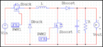
I am referring to the circuit attached in the image here.
My concern is when the diodes are replaced by MOSFETs for synchronous rectification...
The high side buck MOSFET will have to remain ON through if the circuit is operating under boost mode. And in the buck mode it will be desirable to have the boost diode (MOSFET) ON continuously. This continuous ON period is will not allow the conventional bootstrap method for high side MOSFETS.
One way could be to use isolated supplies. Is there some other gate driver circuit/IC that is "commonly" used for this type of converter?
I am of the opinion that a dedicated buck + boost converter will have better noise performance and power handling capability than a typical buck-boost converter. Am I correct?
Thank you
I am wondering what kind of gate driver is used for a non inverting buck+boost converter. (Not the normal buck-boost).
I am referring to the circuit attached in the image here.
My concern is when the diodes are replaced by MOSFETs for synchronous rectification...
The high side buck MOSFET will have to remain ON through if the circuit is operating under boost mode. And in the buck mode it will be desirable to have the boost diode (MOSFET) ON continuously. This continuous ON period is will not allow the conventional bootstrap method for high side MOSFETS.
One way could be to use isolated supplies. Is there some other gate driver circuit/IC that is "commonly" used for this type of converter?
I am of the opinion that a dedicated buck + boost converter will have better noise performance and power handling capability than a typical buck-boost converter. Am I correct?
Thank you