Continue to Site

Welcome to EDAboard.com

Welcome to our site! EDAboard.com is an international Electronics Discussion Forum focused on EDA software, circuits, schematics, books, theory, papers, asic, pld, 8051, DSP, Network, RF, Analog Design, PCB, Service Manuals... and a whole lot more! To participate you need to register. Registration is free. Click here to register now.

How to get voltage gain from a CE amplifier stage that is DC coupled?

Status
Not open for further replies.

thederke

Newbie level 6
Joined
Dec 5, 2016
Messages
13
Helped
1
Reputation
2
Reaction score
1
Trophy points
3
Activity points
149
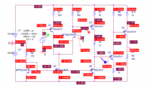
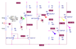
So, this should be a simple question, but I've looked through textbooks and online and while everyone says how to SOLVE a CE amp, I'm having a hard time finding anything on designing for voltage gain. Voltage gain is Vout over Vin I thought? I seem to have a negative gain on my CE stage here (Q4) and just need a gain of maybe ten (total gain of 1000-1500 for amplifier). I've been playing with the R values so don't take them as gospel, ideally for maximum swing Ill use the level shifter Q3 to bring the voltage at the base of Q4 close to 0. I can also connect it to the current mirror and steer it, but I'm not sure how much current is needed. I seem to get better performance from not including it in the current mirror.

tl;dr how do I get gain out of the CE stage? Any way I can do this without using any PNPs (I have NPNs on hand)? Thanks in advance.
 

Attachments

  • output.PNG
    output.PNG
    27.9 KB · Views: 50
  • circuit.PNG
    circuit.PNG
    30.1 KB · Views: 63

A CE amplifier is inverting. It MUST have negative gain. A first-order approximation is vgain=-Rc/Re
 

I thought CE's were used for gain stages, and that referred to just the phase shift of the circuit? Assuming that's correct, if I raise Rc and lower Re, I cant seem to maintain active mode biasing for the transistor. What are the tricks for fixing that?
 

One approach you can try is to make stages alternating NPN and PNP. Biasing is easily achieved from one stage to the next, if you install correct resistors.
 

One approach you can try is to make stages alternating NPN and PNP. Biasing is easily achieved from one stage to the next, if you install correct resistors.

Was really trying to avoid PNP since I have a bunch of NPN on hand but no matching PNP.. however that might end up being what I have to do.
 

OK so Im still stumped here. The NPN part Im using is 2N3663, there's no PNP complement that I can find, and any through-hole NPN I try to replace it with needs to have an ft of at least 2Ghz (according to professor for bandwidth requirements). So I may be stuck using just NPNs.

I seem to kinda get some of the AC range back that I lose with the level shifter but I'm stuck trying to move one R without messing up everything else's dependencies. Can't seem to figure out what to adjust to get that sweet, sweet CE gain
 

Attachments

  • wave1.PNG
    wave1.PNG
    46.6 KB · Views: 55
  • circuit1.PNG
    circuit1.PNG
    39.6 KB · Views: 60

I'm not going to analyze your entire circuit, but here's what I can tell you. The gain of Q4 is about 2.7. From the voltages shown on your schematic, it looks like Q4 is biased reasonably. Can you explain what your actual problem is?
 

I'm not going to analyze your entire circuit, but here's what I can tell you. The gain of Q4 is about 2.7. From the voltages shown on your schematic, it looks like Q4 is biased reasonably. Can you explain what your actual problem is?

Trying to raise the gain on CE from 2.4 to more like ten. I wanna know what exactly to raise, or what to hold constant. Adjusting the Re or Rc resistors changes other things in the circuit that seem to not allow me to raise the gain any higher, so I'm wondering if Vbe is what matters, or should Ic be at a certain value etc.
 

As I said in a previous post, the gain is the ratio of Rc/Re. Start with that. Then set your bias so that your quiescent point places your collector voltage far enough away from the rails.
 

What's the intended amplifier bandwidth? The level shift resistors will seriously constrain it.
 

Status
Not open for further replies.

Part and Inventory Search

Welcome to EDABoard.com

Sponsor

Back
Top