Continue to Site

Welcome to EDAboard.com

Welcome to our site! EDAboard.com is an international Electronics Discussion Forum focused on EDA software, circuits, schematics, books, theory, papers, asic, pld, 8051, DSP, Network, RF, Analog Design, PCB, Service Manuals... and a whole lot more! To participate you need to register. Registration is free. Click here to register now.

SCR failing to turn on during specific firing angle range

Status
Not open for further replies.

pradhan.rachit

Full Member level 3
Joined
Oct 30, 2013
Messages
161
Helped
22
Reputation
44
Reaction score
22
Trophy points
18
Location
Mumbai
Activity points
1,183
Dear experts,

I'm working on a firing angle controller to trigger Semikron's SKCH40/12 Semi-controlled rectifier. Attached is the firing scheme used to trigger the module. The pulse transformer used is a Rp4503 type pulse transformer.
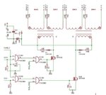
doubt.JPG

1. At first, the firing scheme was such that a 500 us pulse was generated at the firing angle. This works with resistive loads, but as soon as an LC filter is connected for filtration, the SCR fails to turn on properly between 100 degress and 80 degrees and causes severe voltage fluctuation. To solve this, a dummy load was placed before the LC filter to satisfy the latching current requirement, but the SCRs still fail to turn on.

2. The firing scheme was changed by subjecting the gate to a continuous pulse train of 4kHz @ 50% duty cycle. The AC RMS current taken by the gate is 200mA which is higher than the gate requirement of SKCH40/12, but the problem is persistent.

Could someone point out a way to solve this problem? Thank you.
 

My first thoughts are that the IRF540 needs about 4V on its gate before it starts conducting and a voltage of about 8V before it is fully on. The 75AC08 is only rated for 5V operation so it probably isn't able to fully drive the MOSFETs.

Brian.
 

Thanks. But the RMS gate current is close to 200 mA, as measured by a multimeter. Do you still think that the MOSFET is not being sufficiently turned on?

- Rachit
 

Hi,

I doubt that the RMS gate current is 200mA.

Klaus
 

Hi KlausST, I've measured the gate loop and have reported the readings. The input to the rectifier was 120Vrms and the connected load was a 40-ohm heater.

The firing problem lies only in the 90 degress +/- 10 degrees case. The triggering is proper in the other regions. Can you tell why there is this inconsistency?
 

Hi,

I've measured the gate loop and have reported the readings
In your circuit there are just two gates: the gates of the Mosfets.

But reviewing the hole thread I now understand you measured the SCR gate current.
So 200mA could be true.

But the value alone doesn't tell much. The current may flow at wrong timing or with wrong direction.
Can you show the SCR connections?

Klaus
 

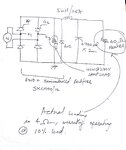
Attached are the connections after the schematic in post #1. There is a resistive load connected to fulfill the latching current requirement of the SCR because there is heavy inductive loading. The sanctioned load is 4 ohms but the system also has to operate on 10% load for which the tests have to be done.

circuitSpecs.jpg

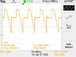
Attached are the waveforms, TEK0035 is the waveform when the firing angle is lesser than 80 degrees.

TEK0035.JPG

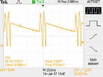
When it is between 90 and 100 degrees (TEK0032), the following waveform is observed. The SCR refuses to latch, and thus there is no input to the LC filter, while the diode freewheels during that duration.

TEK0032.JPG

I even tried with a continuous pulse generation by driving the gate using a opto-coupler and current buffer, while fulfilling the minimum gate current requirements.

Still unclear where I'm falling short. Thanks!
 

Quite obviously, the SCR is not continuously triggered in the second waveform. And triggering - if it happens - is apparently around 30 degree after voltage zero crossing (Vin = Vpk/2), not 90 degree.

You would preferably show the voltage along with the trigger signal.
 

I'm not having access to an isolated scope to record the waveforms to measure Vgk on the high side and the output accross the semiconverter simultaneously.

Any way to go around it?
 

Perhaps you can show the primary trigger signal along with the SCR output as a first step?
 

Dear everyone,

Thanks for all your inputs.

I was able to get my hands on an Isolated DSO, and was able to probe Vgk, Vo and Vin simultaneously. As FvM pointed out, the SCR was not getting triggered because the pulses were not being generated.

Upon further investigation, it was found that the 5mH/25A inductor was the only problem causing element in the system as it worked in case only a C filter was used.

The input to the SCR is via a 230V/120V 2.8kVA transformer, and the firing was generated after tapping the secondary for ZCD reference. This problem of pulse skipping was solved after taking the reference from the primary instead. The LC filter was maintained for the same and thus we didn't have problem in retaining the L for filtration purposes.

Any clues on why it happened? Was it EMI that was getting reflected on to the control side causing this havoc? Thanks.
 

Now that you have access to an isolated DSO, measure the ZCD phasing relationships between the transformer's primary and secondary.

Also, the ZCD's schematic would be helpful.
 

Status
Not open for further replies.

Similar threads

Part and Inventory Search

Welcome to EDABoard.com

Sponsor

Back
Top