Continue to Site

Welcome to EDAboard.com

Welcome to our site! EDAboard.com is an international Electronics Discussion Forum focused on EDA software, circuits, schematics, books, theory, papers, asic, pld, 8051, DSP, Network, RF, Analog Design, PCB, Service Manuals... and a whole lot more! To participate you need to register. Registration is free. Click here to register now.

Problem with Bridge Rectifier

Status
Not open for further replies.

gauravkothari23

Advanced Member level 2
Joined
Mar 21, 2015
Messages
640
Helped
5
Reputation
10
Reaction score
4
Trophy points
1,298
Activity points
6,922
Hi all..
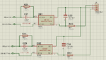
i am attaching a circuit diagram of two bridge rectifier connected in parallel who's GND is shorted and positive rail in connected to PIN 1 and PIN 3 of J1.
and the 220V LINE input to both the bridge rectifier is from Relay NO and Relay NC and 220V neutral is connected directly and also shorted together. so at a time only one rectifier gets activated.
so my problem is when one bridge rectifier gets activated, i get the DC voltage at other rectifier also....
i mean to say that if relay NO is activated, i also get DC voltage at DB2 output, but not any AC voltage and DB2 input.
due to which both the DC lines get activated. how is it possible.
 

Attachments

  • Bridge Rectifier.png
    Bridge Rectifier.png
    37.8 KB · Views: 85

Almost certainly it is through stray wiring capacitance. Without any load, don't forget the capacitor on each output will stay charged even though the input has been disconnected by the relay.

It looks like this could be an un-isolated AC switch so be very careful, even the 'off' half of the circuit can carry lethal voltages.

Brian.
Yes.... But it will be charged for just few seconds... Once it get discharged due to the load connected it has to get off... Which it doesn't.
I even tried removing the capacitor... But the result does not changed.
 

Then I suspect you will have to break the neutral as well as the live of the AC to each half of the circuit. There is probably still path through the load and other bridge rectifier to allow current to flow.

Brian.
 

A slightly different circuit (basically two single wave rectifiers) would work.

Apart from using unsuitable bridge rectifiers, the circuit lacks a voltage limiting means. It feeds about 300 V into open circuit output, destroying the 60V capacitor.
 

Hi,

Why not using only one rectifyer circuit and place the rely at it's output?

Klaus
 

Hello gauravkothari23,
How are you powering your relay/s? Via your rectified outputs: Pins 1 and 3 of JP1?

so my problem is when one bridge rectifier gets activated, i get the DC voltage at other rectifier also....
Depending on the rated voltage of the relay, and you're supplying it with the rectified output, there is a possibility that
the relay is chattering. i.e. continually switching between the two rectifiers.
It might be best if you use two relays, one to switch the active and the other the neutral lines. This will ensure the two
circuits remain isolated from each other.
Also, what type of circuit are you using for the switching the relay/s? As by my calculations, you should be getting
around 10 volts output to J1. If you're trying to use a 12 volt relay, then chatter will likely occur.
If you are powering the relay/s with the outputs, then you need to use a 5 or 6 volt rated relay with a dropping resistor
to suit.
Lastly, I hope you realize that you're working with a circuit at mains potential and can be extremely dangerous.
You also need to make sure you use X-rated capacitors of at least 400WV on the AC input and the two 470k resistors
rated at least 1 watt each.
Regards,
Relayer

- - - Updated - - -

P.S. I meant to mention also that what voltage you could be reading in the turned off rectifier circuit when being switched
could be due to the 22uF capacitor discharging...
Try measuring the off circuit after 20 seconds or so.
Regards,
Relayer
 

Effective impedance of the 0.22uF caps at 50Hz will be about 10-20K and that will limit the current to about 20-30mA. But there will be no limit on the voltage and your output caps can reduce the output impedance...

You should put a bleeding resistor in parallel with the output filter caps. Also make all caps 400V.
 

Status
Not open for further replies.

Part and Inventory Search

Welcome to EDABoard.com

Sponsor

Back
Top