Continue to Site

Welcome to EDAboard.com

Welcome to our site! EDAboard.com is an international Electronics Discussion Forum focused on EDA software, circuits, schematics, books, theory, papers, asic, pld, 8051, DSP, Network, RF, Analog Design, PCB, Service Manuals... and a whole lot more! To participate you need to register. Registration is free. Click here to register now.

Help with IC555 Circuit

Status
Not open for further replies.

ericngy

Newbie level 3
Joined
Sep 5, 2017
Messages
4
Helped
0
Reputation
0
Reaction score
0
Trophy points
1
Location
Singapore
Activity points
43
Dear Esteemed Members,

I am newbie here. It's exciting to see so many circuits and discussions here.
I hope to add my circuit to the discussion. My circuit is not working.

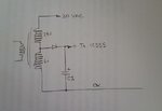
I think it is because my IC555 Output Pin 3 is sending too low a current and hence cannot activate BC548. My circuit is as follows :

EMF Timer Circuit Pain.png

The IC555 datasheet says output current is 0.1A. But I have looked at many circuits on various websites and they use 9V and 1K ohm resister at R5 position. I don't understand that. Won't that generate only 9V/1K ohm = 0.009A only? How can it give 0.1A to activate the BC548 base pin? Anyway I st up the circuit on a standard PC Board and it did not work.

Any suggestion on how to make it work? Can I simply do away with R5 altogether and connect pin 3 to the BC548 base pin directly?
 

That isn't the problem and the circuit can not possible work as you have it.

There are two major flaws in the design:
1. The output of the 555 has to be synchronous to the AC but it free runs so the triac trigger could be anywhere in the AC cycle.
2. The gate voltage has no reference, the current from the transistor to the gate has no path to follow.

To make it work so the variable resistor controls the current through the electromagnet, move it to the top side of the triac and connect the bottom of the triac to pin 1 of the 555.
Remove the connection from the bottom of the transformer to the load completely. That will let the 555 trigger the triac properly, at least in SCR mode.

The next problem is the 555 itself, it needs to work in monostable mode, not astable and the trigger signal to reset the monostable has to come from the transformer. The idea is that you create an adjustable delay from some part of the AC waveform, preferably the zero crossing point, then after that delay you trigger the triac.

To be honest, I think you would do better to remove the 555 completely and wire the circuit as a standard phase controller, it should work if you copy the circuit for a lamp dimmer.

Brian.

Dear Brian,

Thanks for your comments.
I used the IC555 to pulse the current at variable frequency via the potentiometer. The objective is to create a pulsing magnetic field so that when I place a permanent disc magnet near it, the disc will rattle and fly around in a box at different speeds according to the frequency of the pulse. If I move the potentiometer, I will not be able to vary the frequency of the pulse.

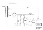
But I get your point. Thanks for pointing out the flaw in my original circuit. I have modified my circuit according to your suggestion. Here is my modified circuit :

EMF Timer Circuit Modify 1 Paint.png

Is this what you mean? If so, I will try it out on my PC Board.
 

I understand the purpose now.

It still won't work as it is, you need to make two changes:
1. move the load to the other side of the triac (in series with R1) and 'short out' its present location.
2. one of the bridge rectifier diodes is shorted and one is across the transformer, you must remove the wire leading directly down from the bottom of the transformer.

Those changes will make it work but I still have doubts whether it will do what you want. The current through the electromagnet will be pulsed DC so an SCR would probably be better than a triac and it might help to add a clamp diode across the load to limit back EMF. You will have to try it to be sure. If you need the load to carry AC, a different trigger circuit will be needed.

Brian.
 

Hi,

additionally your rectifier won´t work this way.
Left top diode will cause a short during one half wave.

--> use only one diode (right top) in half wave rectifier mode.

Klaus
 

Hi Brian and Klaus, I do not quite understand your latest comments. Does it mean that the Transformer cannot output on different taps the 6Vac and 24Vac at the same time? My Transformer has 4 output taps. So I thought I can use two output taps for 6Vac and another two for 24Vac at the same time. If this is not possible, I'll have to use the 24Vac for both the Load and the IC555. Which means I'll have to find a way to convert the 24Vac to 12 Vac for the IC555? Any suggestion on how to do this?
 

Hi,

your circuit shows only three transformer secondary outputs.

***
Is the recommended "single diode solution" too simple?

Klaus
 

Like this Ericngy:
20170906_190640a.jpg20170906_190632a.jpg

Note the different voltages available to the load but the 555 has the same voltage to it.

Brian
 

Yes, my circuit shows 3 tabs with both the 6Vac and 24Vac sharing the same tab at one end.
Thanks Brian for your sketch. I will try out your suggestion and revert by this weekend with the result.
 

Status
Not open for further replies.

Similar threads

Part and Inventory Search

Welcome to EDABoard.com

Sponsor

Back
Top