Continue to Site

Welcome to EDAboard.com

Welcome to our site! EDAboard.com is an international Electronics Discussion Forum focused on EDA software, circuits, schematics, books, theory, papers, asic, pld, 8051, DSP, Network, RF, Analog Design, PCB, Service Manuals... and a whole lot more! To participate you need to register. Registration is free. Click here to register now.

How to recognize those radio RF IF transformers, cans? How to find datasheets?

Status
Not open for further replies.

Garyl

Full Member level 5
Joined
Mar 28, 2017
Messages
253
Helped
6
Reputation
12
Reaction score
7
Trophy points
18
Activity points
2,633
I really want to learn some of the analogue stuff and I know that I need to have IF cans for that.
They are used in many radio receivers and transmitters circuits.

I have looked into my stockpile and found that:
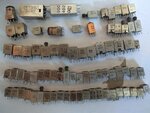
IMG_20170829_145107.jpg

Then I tried to find datasheets for them, and....
... I realized that searching for their codes in Google gives literally nothing!
There are no information, no datasheets, not a single mention of those cans...


Am I doing something wrong, or what's the matter? Is there really no information, no datasheets of IF "can" transformers?
Can anyone help me?


PS: I am attaching a high-res photo of my IF transformers collection, maybe someone can at least recognize few of them? 455kHz, maybe?
 

There are plenty of data sheets for IF transformers. Unfortunately, you don't have a part number for yours. You can take several approaches: You can look at the various manufacturers of IF transformers and see if you can find some match between the number on your device vs. the manufacturer's data. You can test the transformers and determine the inductance, frequency, etc. Or you can just buy the right transformer for your application.

But you don't "need to have IF cans" to learn analog stuff. You only need to have IF cans if you're trying to build a radio.
 

Cans like those are made to order, usually from backstreet Chinese companies so they do not exist as standard components you would find in a catalog. There used to be a company making standard inductances called Toko. The company still exists, in fact it is a major manufacturer but I don't think they still make a standard range of 10mm coils.

So the numbers on them will be 'house codes' for a specific make and model of receiver. Almost certainly many of them will be identical or very similar but the number printed on them has no relationship to their properties.

Brian.
 

Yea, I focus mainly on radio stuff.

I've been thinking about it again and searching and I arrived at conclusion that the only reasonable way to use recycled cans is to check the board schematic before desoldering stuff. Next time I'll have some radio or tv to scavenge I will try to find schematic first and note the can types....
 

I have a few salvaged ones here. Before removing them from the original board I write their purpose on the side of the can, for example "455KHz First IF", "10.7MHz discriminator" to help identify them later. In most cases I do as you did and remove the old wire and wind a new one as needed. Be careful to remove any capacitors, you often find one sitting in a slot between the pins, if you leave it in place the coil will not work.

Brian.
 

I have a few salvaged ones here. Before removing them from the original board I write their purpose on the side of the can, for example "455KHz First IF", "10.7MHz discriminator" to help identify them later. In most cases I do as you did and remove the old wire and wind a new one as needed.
Now I realize that, the bad thing is that in the past I desoldered a lot of them without realizing that their serial numbers won't help me.


Be careful to remove any capacitors, you often find one sitting in a slot between the pins, if you leave it in place the coil will not work.
Strangely enough, those capacitors looks like that older big SMD resistors to me. It's kinda hard to remove them, I've broken of the part of plastic along with pin while doing that, but I managed to glue it back.

Btw, that metal shielding of the can is necessary for it to work correctly?
 

The can is for shielding. It isn't critical in your application as the gain is low and none of them carry large signals. The can is really important where there is a risk of the signal coupling magnetically from one transformer to another. Use the can if possible but don't lose sleep if you can't fit them.

Brian.
 

Okay, so now let's get more specific.

I want to build SES080 QRP transceiver.
Here is the .doc instruction and the .pdf scan of original article:
View attachment SES080 QRP QUARTERLY051.pdf

View attachment SESE80 MANUAL[1]rev2.doc

Here is the components list:
DESIGNATION DESCRIPTION/MARKING PART #
T1, T2, T3 10.7 MHZ IFT 42IF123-RC
Q1 THRU Q8 2N3904 2N3904
U1 78L05 TO92 PACKAGE 78L05ACPRAG
U2 LM386 8 PIN DIP NJM386D
X1 THRU X5 10 MKZ CRYSTAL FOX100-20-LF
C1 THRU C15 .1 UF DISC LABELED AS 104 SR2115E104MMA
C16 THRU C21 390 PF COG BLUE, NO MARKING K391J15COGF53L2
C22 33 PF COG BLUE BODY 33 RPE5C1H
C23-C28 68 PF COF BLUE BODY NO MARKING FK28COG1H680J
C29 .047 UF 140-50Z5-472M-RC
C30-C33 10 UF 16V UVR1E100MDD
C34-C35 100 UF 25V B41827A5107M00
C36 50 PF TRIMMER 659-GKG50015
D1 1N4001 512-1N4001
R1 33K ¼ COLOR CODE OR-OR-OR-GD 291-33K-RC
R2 22K 1/4 W COLOR CODE RD-RD-OR-GD 291-22K-RC
R3 2200 1/4 W COLOR CODE RD-RD-RD-GD 291-2.2K-RC
R4, R5 10K 1/4 W COLOR CODE BR-BK-OR-GD 291-10K-RC
R6 1000 1/4W COLOR CODE BR-BR-RD-GD 291-1K-RC
R7,R8 6800 1/4 W COLOR CODE BL-GY-RD-GD 291-6,8K-RC
R9- R10 1500 1/4 W COLOR CODE BR-GN-RD-GD R291-1.5K-RC
R11 THRU R20 3300 1/4 W COLOR CODE OR-OR-RD-GD 291-3.3K-RC
R21 THRU R23 10 1/4 W COLOR CODE BR-BK-BK-GD 291-10-RC
R24 R25 470 1/4 W COLOR CODE YL-VI-BR-GD 291-470-RC
R26 100 1/4 W COLOR CODE BR-BR-BR-GD 291-1K-RC
R27- R28 330 1/4 W COLOR CODE OR-OR-BN-GD 291-330-RC
RFC1-RFC2 470 UH YL-VO-BR-GD BLUE BODY 542-78F471-RC
VR1 5K AUDIO TAPER RV120F-10-15F-A5K
VR2 100K AUDIO TAPER RV120F-10-15F-A100K
VR3 5K LINEAR TAPER RV120F-10-15F-L100K
J1 SPEAKER JACK 1/4" 161-MJ159M-EX
J2 PWR JACK 5.5 MM/2.1MM 163-4304-E
J3 SO239 ANTENNA CONNECTOR USER SUPPLIED
KNOBS USER SUPPLIED
12V DC POWER SUPPLY USER SUPPLIED
CABINET USER SUPPLIED

As you see, it requires three IF cans: 10.7 MHZ IFT 42IF123-RC.

First, I have looked at Aliexpress, because that's where I but parts.
Obviously, there was nothing like that IF can.

Then I checked the Google,which led me to Mouser. Unfortunatelly, the 42IF123 is marked as "Obsolete" and "Not Available" in Mouser.

The only place which is apparently selling such cans, each for 3$ (!!!), is located in Southern Australia.... and I live in the Europe...

Is this really that hard to get proper IF cans? Or maybe can I somehow replace them, or find the replacements in the old electronics junk?
 

Bear in mind they are not being used as 10.7MHz IF transformers. The reason those particular types were chosen is they are designed to work at 10.7MHz, a little higher than 3.5MHz, and the nature of LC parallel circuits is that adding external capacitance lowers the resonant frequency. You could use a wide range of coils as long as the capacitance across them tuned them to 3.5MHz. You could use any of the ones in your picture if you remove the original coil and tuning capacitor then wound our own coil back on the plastic former.

If you look closely at the circuit and do some mental rearranging, you will note it is almost the same as the VK3AJG design, the only significant difference being the 10MHz IF filter and BFO which make it a superhet design rather than direct conversion.

Personally I would make some changes:
rfc02 would be a 10K resistor.
C11 would be 1uF
C29 would be across the volume control instead of to +12V
D1 would be a varicap instead of a 1N4001
however, it should still work as it is.


Brian
 
  • Like
Reactions: Garyl

    Garyl

    Points: 2
    Helpful Answer Positive Rating
The datasheet parameters allow to locate a similar part or even wind it yourself.

You are right that finding the datasheet on Mouser is not hard, but what about finding the IF can for given parameters?
I really wanted to order them from Aliexpress, but it turned out that there are no such parts there at all!

You could use any of the ones in your picture if you remove the original coil and tuning capacitor then wound our own coil back on the plastic former.
Can you give me more information how would I do that? Recently I have bought an inductance meter, but I have mixed feelings about its accuracy. I also have the scope.

Can I somehow prepare my replacement for this can totally outside the circuit? Well, I guess I'd have to just measure the coil frequency and then do the math to select the capacitor... most likely there
So I would only wind the coil, and place the capacitor outside the can?


If you look closely at the circuit and do some mental rearranging, you will note it is almost the same as the VK3AJG design, the only significant difference being the 10MHz IF filter and BFO which make it a superhet design rather than direct conversion.
I realized that, but I watched videos of people testing it and the voice quality was very good...


Personally I would make some changes:
rfc02 would be a 10K resistor.
C11 would be 1uF
C29 would be across the volume control instead of to +12V
D1 would be a varicap instead of a 1N4001
however, it should still work as it is.
Right now I haven't analyzed those changes, but I'll keep them in mind when the time comes. Maybe I will post a new topic for this receiver in the appropriate forum, especially cause your hints are extremally helpful and I appreciate that. Thanks!
 

You could use any of the ones in your picture if you remove the original coil and tuning capacitor then wound our own coil back on the plastic former.

So,
1. remove capacitor
2. remove winding
3. according to 42IF123 datasheet:
42IF123Datasheet.png
I should wind 5+9 (14) turns between pins 1 and 3 (because center tap is not used on schematic)
and wind 2 turns between pins 4 and 6?

Is my understanding correct? Also, how do I wind that, I mean, which winding of top of which? And they should have the same winding direction, right?
 
Those figures are for pre-wound and tuned transformers, ready to drop into specific applications. It would be better to add turns to get the right inductance which you can calculate then measure as you wind the coil. The resonant frequency depends not only on the coil but the capacitance across it (f=1/2*pi*sqrt(L*C)).

If you initially wind say 20 turns then measure the inductance, you can get an approximation of how much each turn produces by dividing the result by 20. It isn't exact because of other factors like the capacitance to the core and the inductance of the 'tails' on the wire to the pins but it will be good enough to work with. You should get around 5% adjustment range anyway as you turn the core. If the transformer has an external ferrite shield, make sure it is in place when you measure the inductance!

Brian.
 
  • Like
Reactions: Garyl

    Garyl

    Points: 2
    Helpful Answer Positive Rating
Those figures are for pre-wound and tuned transformers, ready to drop into specific applications. It would be better to add turns to get the right inductance which you can calculate then measure as you wind the coil. The resonant frequency depends not only on the coil but the capacitance across it (f=1/2*pi*sqrt(L*C)).

You could use a wide range of coils as long as the capacitance across them tuned them to 3.5MHz

3.5MHz=1/2*pi*sqrt(L*390pF)
http://www.daycounter.com/Calculators/LC-Resonance-Calculator.phtml
5.30e+3nH = 5300nH
checked by http://www.ham-radio.com/lc.html

So, for the 390pF capacitor from the schematic I have to wind 5300nH winding?

But.... I can first wind winding and then select the capacitor to match the 3.5 MHz frequency?

It's getting more clear now, but It's now obvious that I need ACCURATE measurement tools for both inductance and capacitance...
 

5302nH to be exact!
Yes, you can adjust the capacitor to 'fine tune' the filters. Technically, the different values will alter the shape of the filter bandwidth slightly but it would be such a tiny amount you wouldn't notice. Don't forget you get maybe +/- 2.5% variation of inductance by adjusting the core in the coil as well so try that before resorting to additional adjustable capacitors.

Brian.
 
  • Like
Reactions: Garyl

    Garyl

    Points: 2
    Helpful Answer Positive Rating
Well, since it all comes down to having accurate measurement equipment, I've started looking for DIY LC meters and found that:

http://sites.google.com/site/vk3bhr/home/index2-html

An "improved" inductance / capacitance meter by Phil Rice VK3BHR - a club project of the Midland Amateur Radio Club - http://www.marc.org.au


That's the PIC16F628-based LC meter:
LCM2.gif
And they even attach the PCB tracks image:
View attachment LCMx1.pdf

Description:
No particularly accurate components are required, except for one (or more) accurately known "external" capacitors used to calibrate the meter.
The two 1000pF capacitors ("C" and "Ccal") should be fairly good quality (stability is important, accuracy is not ;-). Polystyrene are preferred. MKT are fine, as are Mica. Greencaps tend to drift in value too much. Avoid ceramic capacitors. Some of these can have high losses (and it is hard to tell).
The two 10uF capacitors in the oscillator should be NEW tantalum ones (for low series resistance/inductance). Alternatively, "low ESR" aluminium capacitors can be used. You could add a 0.01uF ceramic capacitor in parallel with each, "just to be safe".
The 4MHz crystal should be a genuine 4.000MHz one, not something approximate to 4MHz. Every 1% error in crystal frequency adds 2% error to the indicated inductance value.
The relay should be a low current one. The PIC can only provide about 30mA of drive current. The relay should be able to "pull in" with 4.5 volt applied to the coil. (Most 5volt reed relays will be OK).
Don't forget the "catch" diode across the relay coil!

The range is said to be:
Code:
Measuring range is from 0 to >0.1uF for capacitance and 0 to >10mH for inductance.

Expected accuracy is +/- 1% of reading +/- 0.1pF or +/- 10nH

Source: http://sites.google.com/site/vk3bhr/home/lcm1 (well, it looks like an older version of that meter)


@betwixt, do you think that this meter is worth trying and will be good enough for my purposes?
 

It should be good enough. The two designs are actually identical but the older one used an external comparator while the newer one uses the comparator inside the microcontroller.
Be sure to use the correct relay type, the coil is driven directly from the PIC so the current available to operate it is quite small. If you use a larger relay it probably won't work and you risk damaging the PIC.

Brian.
 

OZL7 IF can transformer for 40m radio part?

Hey,
what is that TR101/TR102 part on this schematic?
Single_band_HF_SSB_CW_RX_No1_SCH.jpg
From: https://www.qsl.net/g4usp/HF SSB CW RX 1/Single band HF SSB CW RX No1.htm
Label says OZL7 but I haven't found anything in Google for that.

I need to know at leaset the number of turns of both coils in TR101/TR102, but this is also missing from the description:
Detailed here within is a simple crystal controlled receiver originally developed to operate on a single fixed frequency to monitor QRSS transmissions on the 40m amateur band. It can be easily adapted to operate on any of the HF amateur bands by simply altering key component values.


Design concept:

The design concepts primary goals were as follows:

Small and compact design.

Simple, easy to set up and easy to replicate design.

Using easy to source readily available, economic components.

Good performance on today's crowded HF amateur bands.


Receiver description single conversion super heterodyne.

The RF front end section comprising TR101,TR102,C102,C103, & C104 forming a three element Pi band pass filter impedance matched to both the antenna and first mixer IC101 (NE612). Although there is no RF pre-amplifier, the mixer IC101 does provide around 8db conversion of gain.

The receiver operating frequency is set by frequency of crystal Q101 (FQ101 = Frx + IF or FQ101 = Frx - IF). My receivers operating frequency is set to 7.0008MHz in order to monitor QRSS activity on the 40m amateur band, therefore (FQ101 = 7.0008 + 8.0000) 15.0008MHz. In reality the crystal used was 15MHz fine tuned to the correct frequency with padding capacitor CV101. Although it could be easily modified to cover a small section of a single amateur band i.e. the CW section, or for that matter part of the SSB section whilst still maintaining good frequency stability by adopting more aggressive VXO tuning of the crystal local oscillator.

The IF section comprising Q102, Q103, Q104, Q105, C110, C111, C112, C113, C114 form a four pole crystal ladder filter, this is where the bulk of the receivers selectivity is achieved. Here as with the RF front end there is no amplification provided at IF, although again there is around 8db of gain provided by the product detector IC102. Sideband selection being achieved by appropriate adjustment of CV102.

The AF section comprising of active devices T101 and IC104. Components C118, C119, & L103 forming a Pi low pass filter prior to T101 the audio pre amplifier, volume adjustment by RV101 before the final stage the AF power amplifier IC104 capable of providing several watts into an 8 ohm speaker.

The voltage regulator IC103. Providing a stabilised 8volt supply to both IC101 & IC102, this improves the frequency stability of the receiver at less than 15Hz in the first 60 minutes after switch on. Please note bypass capacitors C134 & C135 are essential to eliminate any noise generated by the voltage regulator IC, furthermore chokes L101 & L102, and bypass capacitors C132 & 133 are essential to ensure no noise is introduced to the two mixers IC101 & IC102.
 
Last edited by a moderator:

I don't want to create separate topic for similiar question so I will post here.

Okay, so now let's get more specific.

I want to build SES080 QRP transceiver.
Here is the .doc instruction and the .pdf scan of original article:
View attachment 141085

View attachment 141086

Here is the components list:


As you see, it requires three IF cans: 10.7 MHZ IFT 42IF123-RC.

First, I have looked at Aliexpress, because that's where I but parts.
Obviously, there was nothing like that IF can.

Then I checked the Google,which led me to Mouser. Unfortunatelly, the 42IF123 is marked as "Obsolete" and "Not Available" in Mouser.

The only place which is apparently selling such cans, each for 3$ (!!!), is located in Southern Australia.... and I live in the Europe...

Is this really that hard to get proper IF cans? Or maybe can I somehow replace them, or find the replacements in the old electronics junk?

Bear in mind they are not being used as 10.7MHz IF transformers. The reason those particular types were chosen is they are designed to work at 10.7MHz, a little higher than 3.5MHz, and the nature of LC parallel circuits is that adding external capacitance lowers the resonant frequency. You could use a wide range of coils as long as the capacitance across them tuned them to 3.5MHz. You could use any of the ones in your picture if you remove the original coil and tuning capacitor then wound our own coil back on the plastic former.

If you look closely at the circuit and do some mental rearranging, you will note it is almost the same as the VK3AJG design, the only significant difference being the 10MHz IF filter and BFO which make it a superhet design rather than direct conversion.


So, I have assembled my SESE80 receiver (pdf, doc and schematic in quote above).
I have used BC547 instead of 2N3904 (I have used correct pinout)..
I didn't have the "IF can" for the VFO yet, so I had to choose inductor.
I tested various axial inductors in this circuit with oscilloscope and finally I have chosen 11uH (10uH+1uH to be exact), which gave me range:
Code:
22uH
4*0.05us
5.7*0.05us
33uH
4.7*0.05us
6*0.05uS

4.7uH
1.9*0.05uS
2.2*0.05uS
10uH
2.8*0.05uS
3.2*0.05uS
11uH
3.5*0.05uS
3*0.05uS
11uH
3.5*0.05uS - 5.71MHz
3*0.05uS - 6.66MHz
which, as seen above, gave me range around 5.71MHz-6.66MHz VFO range which is 4.29MHz-3.34MHz tuning range because it's a superhet.

I also didn't have the IF transformers for antenna filter, so I have used antenna filter from other 80m receiver.

Right now my receiver is able to receive the 3.6MHz test signal, but it's clearly disorted:
View attachment sesetest.zip
I can't receive CW or SSB, only sometimes such noise, and I have a bit loud constant hum from speaker (but it doesn't seem to be related to mixers, because it happens even with audio stage disconnected).
I have also added 4.7uF capacitor before volume potentiometer, but it's not changing much...
Can anyone help me figure out what's wrong?
 
Status
Not open for further replies.

Similar threads

Part and Inventory Search

Welcome to EDABoard.com

Sponsor

Back
Top