Continue to Site

Welcome to EDAboard.com

Welcome to our site! EDAboard.com is an international Electronics Discussion Forum focused on EDA software, circuits, schematics, books, theory, papers, asic, pld, 8051, DSP, Network, RF, Analog Design, PCB, Service Manuals... and a whole lot more! To participate you need to register. Registration is free. Click here to register now.

Microlab FC330 Subwoofer won't work

Status
Not open for further replies.

Luxfire

Newbie level 5
Joined
Aug 27, 2017
Messages
9
Helped
0
Reputation
0
Reaction score
0
Trophy points
1
Activity points
84
Hi guys, i've got an Microlab FC330,
They just stop working. Aty first one MOSFET in power PCB didnt work properly so i take care of it.
Now subwoofer won't work, but speakers works well. my guess is a transistor c1858 <datasheet here https://pdf1.alldatasheet.pl/datasheet-pdf/view/30084/TOSHIBA/C1815.html > but i'm not sure with this, could you give me some tips, what to check?
Thank for Your guidiance,

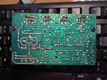
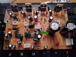
IMG of pcb:
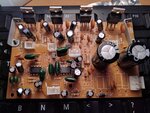
43S4OlX.jpg

KMlFccW.jpg
 
Last edited by a moderator:

hi,

check again for mosfet for sub woofer.
if speaker's mosfet are working then, you can check by changing the mosfet of speaker-sub woofer.
this will help to determine where is fault.

thanks vraj.
 

There is no speaker/subwoofer mosfets, power suply is -12,0,12V, all of power transistors are connected to -12 and 12 V.
when i'm touching red wire which goes from middle pin in 3pin switch at middle of pic to potentiometer<adjusting of subwoofer power> subwoofer slightly scratching.
also between red wire and ground is 0V.
That transistor <c1858> is connected to red wire (collector), ground(emitter), base is connected to another c1858 by 1K resistor and to +12V by 1K resistor and 10K resistor.
 

There are no power transistors on the PCB, only TDA2030 integrated power amplifiers. Apparently they have been already replaced.
 

There is more chances that tda2030a is damaged. Tda2030a is so cheap and difficult to find original one. have experience.
 

so. i checked Tda from subwoofer by swaping subwoofer and speakers tda, as before, only speakers works
 

Hello Luxfire,
Are you referring to Transistor Q2 (Shown red circled in your modified picture)?
From what I can see by zooming in, Q2 seems to have a split on its top.
If it is the transistor you're referring to, then replacements are easily gotten. Its part number is: 2SC1815.
As shown with the green arrow, what is that mass supposed to be?
Regards,
Relayer

43S4OlX - Modified.jpg
 

I've changed two c1815 (Q1 and Q2) unfortunately nothing changed, speakers still running, subwoofer not.
 

If Q2 was physically damaged, as you never mentioned if it was or not, then you need to check all components
that are connected to Q2.
By the way, which two connector/s are for your sub-woofer?
Regards,
Relayer
 

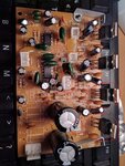
voltage on tda are the same, 1 = 0V, 2 = 0V, 3=-12V, 4=0V and 5= -12VIMG_20170827_095040.jpg 2 Tda, this 3 pin is potentiometer on the back of sub to adjust his power, and 2 pin is subwoofer
 

Luxfire, please check out the modified picture I've put up...

You need to check any components attached to the two signal paths shown. But
when you flip the PCB to the component side, pay particular attention to R10 and
the resistor above it, as these two components are common to both signals.

It would make things a lot easier if you had an AF signal injector, as this will allow
you to check each section of the signal path. Though SunnySkyguy's suggestion is
the next best thing to a signal injector. :lol:
Please let us know how you get on.
Regards,
Relayer

KMlFccW - Modified.jpg
 
Last edited:
So. i've checked it, and all components are good. i also touched signal lines, and speakers 'shouted' and then i realize that this red and green paths are from speakers, not subwoofer, so then i touched 1 pin? leg? of tda2030 from subwoofer and subwoofer starts to 'shout', just doing sound. Voltage are good. where should be -12 therre is -12. now i see, that i got faulty value in my previous post, 5th isnt -12 but +12. sorry for that,
 

@Relayer
Thank You... Thank You very much! We've DONE IT! i've checked voltage again. in dual op amplifier should be -12 and 12. there were only 12 and 0. so i was searching something suspect. Schottky Diode. it was strangly coneccted, so i delete it, plug in and there was -8V, subwoofer back to alive and started 'boom booming'. so. i'm realizing that diode was broken. tomorow i'll go to shop and buy new one. again... Thank YOU ALL so much. i'm really grateful for Your guidiance.
 

Hello again Luxfire,
I appreciate the thanks :wink:, though SunnySkyguy also contributed to your eventual fix. :smile:


Please have a look at the modded picture below.
I can only see 4 diodes in total.
D1 and D2 are 12 volt 400mW Zener Diodes, used to maintain the voltages on the +12V and -12V rails.
D5 could be a Schottky diode (1N5819) or a general rectifier type (1N4002 - 1N4007). Though you should be able
to determine its type by reading its number on the diode body.
D6 would more than likely be a 1N4148 small signal diode.
What is the circuit designation of the diode you need to replace?
If its one of the glass passivated zener diodes (D1 or D2), it wouldn't hurt to replace it with a 1Watt type. In fact, since they
would be relatively cheap, it wouldn't hurt to replace them both.
Please let us know how you get on. And by the way, WELL DONE it getting this problem solved. :-D
Regards,
Relayer

43S4OlX - Diodes.jpg
 

    Enice

    Points: 2
    Helpful Answer Positive Rating
So. I replaced ZD1. Its strange, cause teacher in my school told that Zener Diode have only one vertical line with one horizontal, and Shottky one have something like S. But nevermind. As i said, today i'll buy new one and install it. One more time, Thank You for all that You have done to me,
 
Last edited:

Status
Not open for further replies.

Similar threads

Part and Inventory Search

Welcome to EDABoard.com

Sponsor

Back
Top