Continue to Site

Welcome to EDAboard.com

Welcome to our site! EDAboard.com is an international Electronics Discussion Forum focused on EDA software, circuits, schematics, books, theory, papers, asic, pld, 8051, DSP, Network, RF, Analog Design, PCB, Service Manuals... and a whole lot more! To participate you need to register. Registration is free. Click here to register now.

Can't understand Current Adjustment Function in Lab power supply?

Status
Not open for further replies.

message4guru

Junior Member level 2
Joined
May 23, 2017
Messages
20
Helped
0
Reputation
0
Reaction score
0
Trophy points
1
Activity points
181
Cant Understand Current Adjustment Function in Lab power supply???

Hi to all!!!!

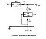
I cant understand the function of LM117 present accross the output. Why it should be connected to negative supply voltage to the output terminal.what is the function of 150 ohm variable resistor?
 

Attachments

  • current regulator.jpg
    current regulator.jpg
    91.9 KB · Views: 70
Last edited:

Re: Cant Understand Current Adjustment Function in Lab power supply???

Not connected across the output. It's an auxiliary 10 mA current source, used as reference for the current controller.

Negative supply makes the constant current source work down to 0V at Iout terminal.
 
Re: Cant Understand Current Adjustment Function in Lab power supply???

Not connected across the output. It's an auxiliary 10 mA current source, used as reference for the current controller.

Negative supply makes the constant current source work down to 0V at Iout terminal.

Sir,

i dont know how to ask my doubt.

1)Please explain the secong LM117 function?
2)why negative supply is given to vout terminal of second LM117?
normally 1.2V will be present between adj pin and Vout pin.
3) what is the function of 150 ohm resistor?

Please explain things with schematics. thank you sir.
 

Re: Cant Understand Current Adjustment Function in Lab power supply???

Hi,

the right bottom LM117 is a constant current source to get a constant voltage across the 150R pot.
Current = 1.25V / 120 Ohms = about 10.4mA (Iadj neglected)

The left top LM117 is the current limiter. The current measurement is the voltage drop across the 1Ohms resistor. (150 Ohms x 10.4mA = 1.56V)
And it is compared/regulated with the adjustable voltage drop of the pot.
With the wiper at the bottom there is about 1.56V between V_out and ADJ of the top regulator, it will not allow any load current to flow.
With the wiper at the top.. the the current will be limited to 1.25V/1Ohms = 1.25A.

Klaus

Dear Sir,

hence second LM117 is constatnt current source supplying 1.56v @ 10.4mA. I should not any more see it as a voltage regulator. It is a current source supplying 1.56v to adjust my output current from the main LM117 regulator. Correct me if iam wrong sir.
 

Attachments

  • LM117.jpg
    LM117.jpg
    21.7 KB · Views: 58

Re: Cant Understand Current Adjustment Function in Lab power supply???

Hi,

Constant current ... means it supplies a current. .. of about 10.4mA.

The 1.56V is just the the voltage that is caused by 10.4mA through the 150 Ohms resistor.

Klaus
 

Status
Not open for further replies.

Similar threads

Part and Inventory Search

Welcome to EDABoard.com

Sponsor

Back
Top